Autonomous Driving
- Humble
- Noetic
Getting Started
NOTE
- The Autorace package was developed for
Ubuntu 22.04runningROS 2 Humble Hawksbill. - The Autorace package has only been comprehensively tested for operation in the Gazebo simulator.
- Instructions for correct simulation setup are available in the Simulation section of the manual.
For ROS2 Humble, our Autonomous Driving package has only been tested in simulation.
Prerequisites
Remote PC
- ROS 2 Humble installed on a Laptop or desktop PC.
Install Autorace Packages
- Install the AutoRace meta package on the
Remote PC.
$ cd ~/turtlebot3_ws/src/
$ git clone https://github.com/ROBOTIS-GIT/turtlebot3_autorace.git
$ cd ~/turtlebot3_ws && colcon build --symlink-install
- Install additional dependent packages on the
Remote PC.
$ sudo apt install ros-humble-image-transport ros-humble-cv-bridge ros-humble-vision-opencv python3-opencv libopencv-dev ros-humble-image-pipeline
Setting World Plugin
Add an export line to your ~/.bashrc, put your workspace name in {your_ws}. This plugin allows you to animate dynamic environments in your world.
$ echo 'export GAZEBO_PLUGIN_PATH=$HOME/{your_ws}/build/turtlebot3_gazebo:$GAZEBO_PLUGIN_PATH' >> ~/.bashrc
Setting TurtleBot3 Model
Add an export line to your ~/.bashrc. Autorace only supports the burger_cam model.
$ echo 'export TURTLEBOT3_MODEL=burger_cam' >> ~/.bashrc
Camera Calibration
Camera calibration is crucial for autonomous driving as it ensures the camera provides accurate data about the robot's environment. Although the Gazebo simulation simplifies some calibration steps, understanding the calibration process is important for transitioning to a real-world robot. Camera calibration typically consists of two steps: intrinsic calibration, which deals with the internal camera properties, and extrinsic calibration, which aligns the camera’s view with the robot’s coordinate system. In Gazebo, these steps are not required because the simulation uses predefined camera parameters, but these instructions will help you understand the overall process for real hardware deployment.
Camera Imaging Calibration
In the Gazebo simulation, camera imaging calibration is unnecessary because the simulated camera does not have lens distortion.
To begin, launch the Gazebo simulation on the Remote PC by running the following command:
$ ros2 launch turtlebot3_gazebo turtlebot3_autorace_2020.launch.py
Intrinsic Camera Calibration
Intrinsic calibration focuses on correcting lens distortion and determining the camera’s internal properties, such as focal length and optical center. In real robots, this process is essential, but in a Gazebo simulation, intrinsic calibration is not required because the simulated camera is already distortion-free and provides an ideal image. However, this step is included to help users understand the process for real hardware deployment.
To execute the intrinsic calibration process as it would run on real hardware, launch:
$ ros2 launch turtlebot3_autorace_camera intrinsic_camera_calibration.launch.py
This step will not modify the image output but ensures that the correct topics (/camera/image_rect or /camera/image_rect_color/compressed) are available for subsequent processing.
Extrinsic Camera Calibration
Extrinsic calibration aligns the camera’s perspective with the robot’s coordinate system, ensuring that objects detected in the camera’s view correspond to their actual positions in the robot's environment. In real robots, this process is crucial, but in a Gazebo simulation, the calibration is performed for consistency and to familiarize users with the real-world workflow.
Once the simulation is running, launch the extrinsic calibration process:
$ ros2 launch turtlebot3_autorace_camera extrinsic_camera_calibration.launch.py calibration_mode:=True
This will activate the nodes responsible for camera-to-ground projection and compensation.
Visualization and Parameter Adjustment
- Execute rqt on
Remote PC.
$ rqt
-
Navigate to Plugins > Visualization > Image view. Create two image view windows.
-
Select the
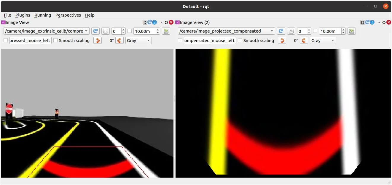
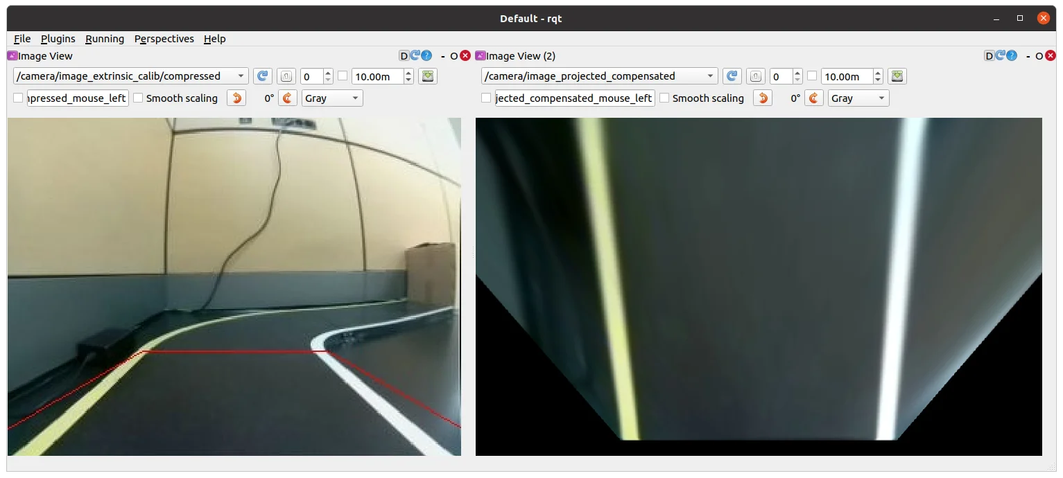
/camera/image_extrinsic_calibtopic in one window and/camera/image_projectedin the other.-
The first topic shows an image with a red trapezoidal shape and the latter shows the ground projected view (Bird's eye view).
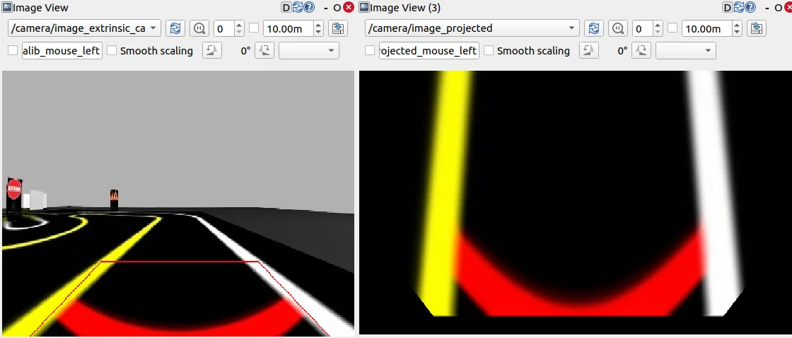
/camera/image_extrinsic_calib(Left) and/camera/image_projected(Right)
-
-
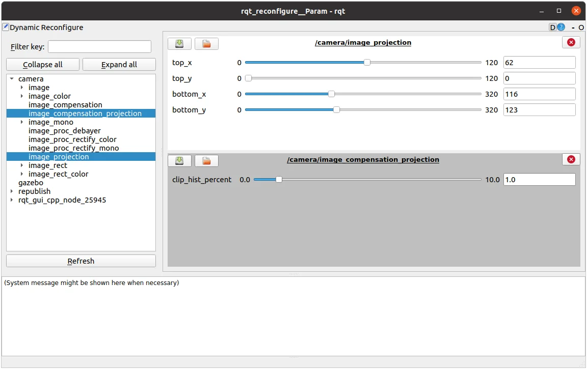
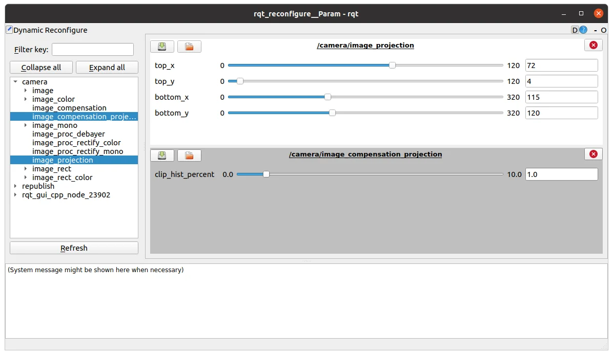
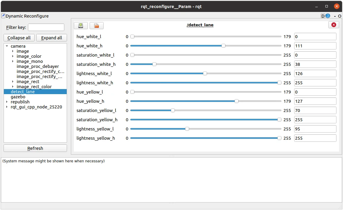
Navigate to Plugins > Configuration > Dynamic Reconfigure.
-
Adjust the parameters in
/camera/image_projectionand/camera/image_compensationto tune the camera's calibration.-
Change the
/camera/image_projectionvalue to adjust the/camera/image_extrinsic_calibtopic. -
Intrinsic camera calibration modifies the perspective of the image in the red trapezoid.
-
Adjust
/camera/image_compensationto fine-tune the/camera/image_projectedbird’s-eye view.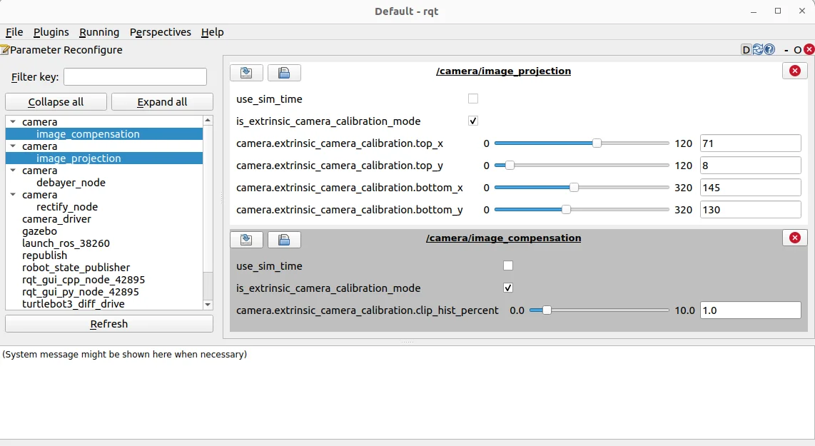
rqt_reconfigure
-
Saving Calibration Data
Once the best projection settings are found, the calibration data must be saved to ensure that the parameters persist across sessions. One way to save the extrinsic calibration data is by manually editing the YAML configuration files.
- Navigate to the directory where the calibration files are stored:
$ cd ~/turtlebot3_ws/src/turtlebot3_autorace/turtlebot3_autorace_camera/calibration/extrinsic_calibration/
- Open the relevant YAML file (e.g.,
projection.yaml) in a text editor:
$ gedit projection.yaml
- Modify the projection parameters to match the values obtained from dynamic reconfiguration.
This method ensures that the extrinsic calibration parameters are correctly saved for future runs.
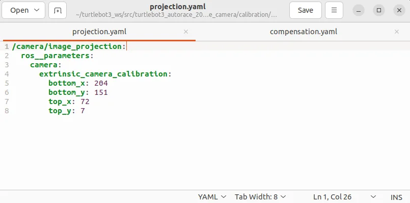
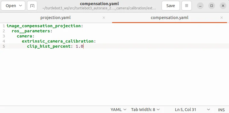
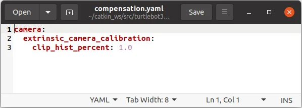
turtlebot3_autorace_camera/calibration/extrinsic_calibration/ projection.yaml (Left) |
turtlebot3_autorace_camera/calibration/extrinsic_calibration/ compensation.yaml (Right)
Check Calibration Result
After completing the calibration process, follow the instructions below on the Remote PC to verify the calibration results.
-
Stop the current extrinsic calibration process.
If the extrinsic calibration was launched incalibration_mode:=True, stop the process by closing the terminal or pressingCtrl + C. -
Launch the extrinsic calibration node without calibration mode.
This ensures that the system applies the saved calibration parameters for verification.
$ ros2 launch turtlebot3_autorace_camera extrinsic_camera_calibration.launch.py
- Execute rqt and navigate Plugins > Visualization > Image view.
$ rqt
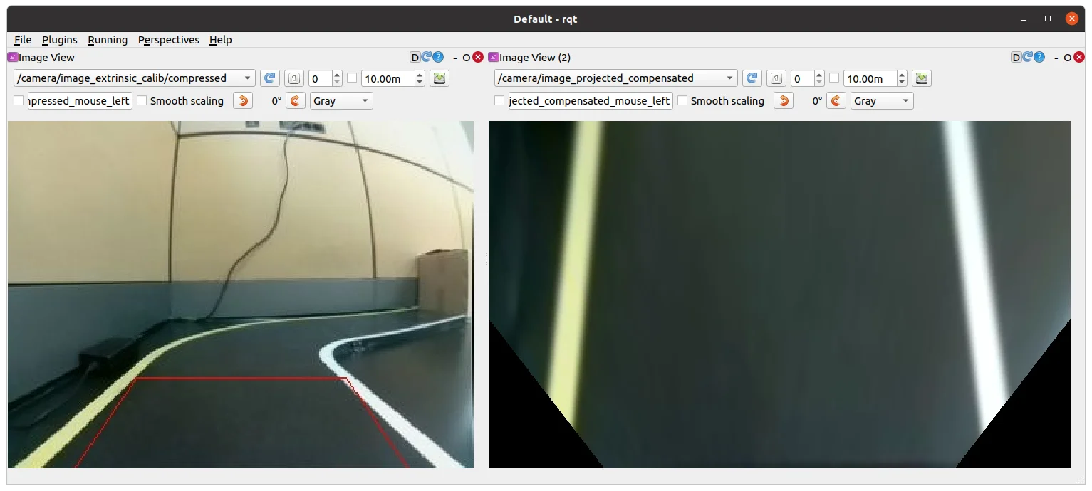
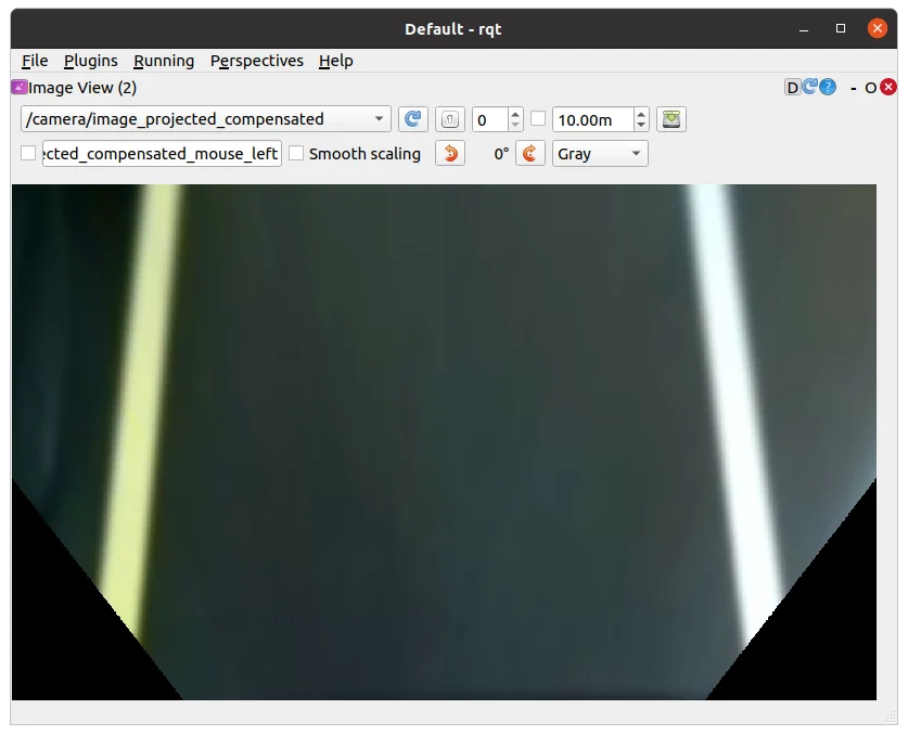
- With successful calibration settings, the bird-eye view image should appear like below when the
/camera/image_projectedtopic is selected.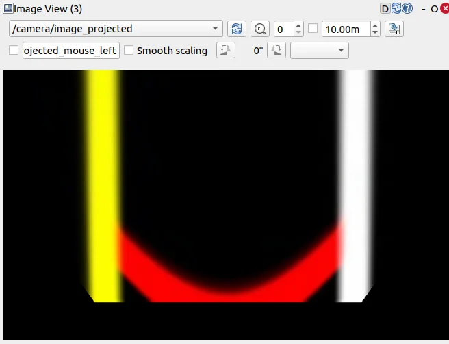
Lane Detection
Lane detection allows the TurtleBot3 to recognize lane markings and follow them autonomously. The system processes camera images from either a real TurtleBot3 or Gazebo simulation, applies color filtering, and identifies lane boundaries.
This section explains how to launch the lane detection system, visualize the detected lane markings, and calibrate the parameters to ensure accurate tracking.
Launching Lane Detection in Simulation
To begin, start the Gazebo simulation with a pre-defined lane-tracking course:
$ ros2 launch turtlebot3_gazebo turtlebot3_autorace_2020.launch.py
Next, run the camera calibration processes, which ensure that the detected lanes are accurately mapped to the robot’s perspective:
$ ros2 launch turtlebot3_autorace_camera intrinsic_camera_calibration.launch.py
$ ros2 launch turtlebot3_autorace_camera extrinsic_camera_calibration.launch.py
These steps activate intrinsic and extrinsic calibration to correct any distortions in the camera feed.
Finally, launch the lane detection node in calibration mode to begin detecting lanes:
$ ros2 launch turtlebot3_autorace_detect detect_lane.launch.py calibration_mode:=True
Visualizing Lane Detection Output
To inspect the detected lanes, open rqt on Remote PC:
$ rqt
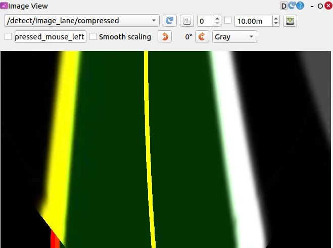
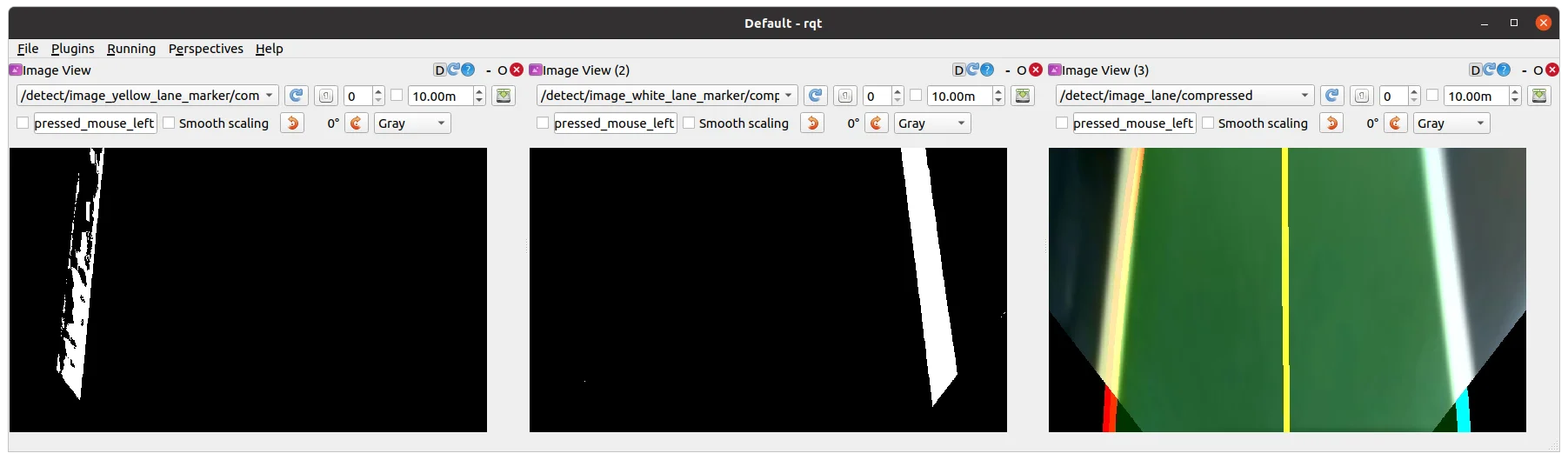
Then navigate to Plugins > Visualization > Image View and open three image viewers to display different lane detection results:
/detect/image_lane/compressed
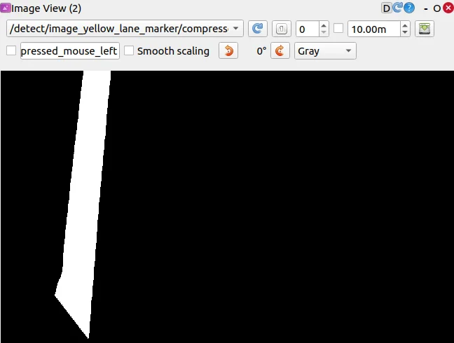
/detect/image_yellow_lane_marker/compressed: a yellow range color filtered image.
/detect/image_white_lane_marker/compressed: a white range color filtered image.
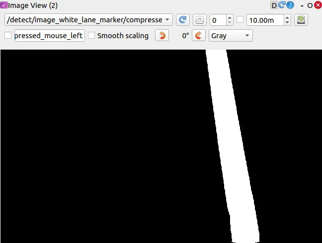
These visualizations help confirm that the lane detection algorithm is correctly identifying lane boundaries.
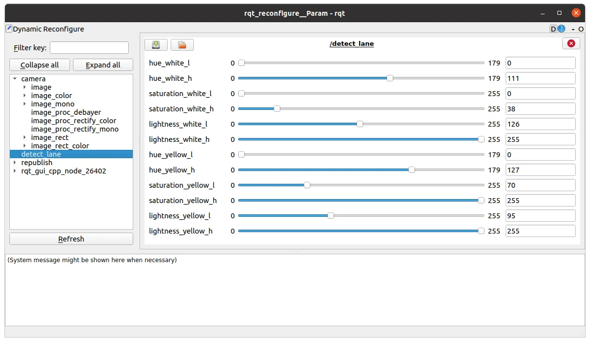
Calibrating Lane Detection Parameters
For optimal accuracy, tuning detection parameters is necessary. Adjusting these parameters ensures the robot properly identifies lanes under different lighting and environmental conditions.
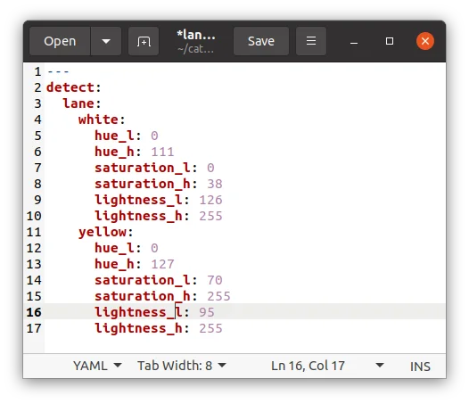
- Open the lane.yaml file located in turtlebot3_autorace_detect/param/lane/ and write your modified values to this file. This will ensure the camera uses the modified parameters for future launches.
$ cd ~/turtlebot3_ws/src/turtlebot3_autorace/turtlebot3_autorace_detect/param/lane$ gedit lane.yaml
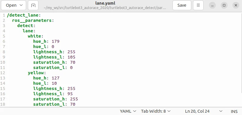
Modified lane.yaml file
Running Lane Tracking
Once calibration is complete, restart the lane detection node without the calibration option:
$ ros2 launch turtlebot3_autorace_detect detect_lane.launch.py
Then, launch the lane following control node, which enables TurtleBot3 to automatically follow the detected lanes:
$ ros2 launch turtlebot3_autorace_mission control_lane.launch.py
Traffic Sign Detection
Traffic sign detection allows the TurtleBot3 to recognize and respond to traffic signs while driving autonomously.
This feature uses the SIFT (Scale-Invariant Feature Transform) algorithm, which detects key feature points in an image and compares them to a stored reference image for recognition. Signs with more distinct edges tend to yield better recognition results.
This section explains how to capture and store traffic sign images, configure detection parameters, and run the detection process in the Gazebo simulation.
NOTE: More and better defined edges in the traffic sign increase recognition results from the SIFT algorithm.
Please refer to this SIFT documentation for additional information.
Launching Traffic Sign Detection in Simulation
Start the Autorace Gazebo simulation to set up the environment:
$ ros2 launch turtlebot3_gazebo turtlebot3_autorace_2020.launch
Then, control the TurtleBot3 manually using the keyboard to navigate the vehicle toward traffic signs:
$ ros2 run turtlebot3_teleop teleop_keyboard
Position the robot so that traffic signs are clearly visible in the camera feed.
Capturing and Storing Traffic Sign Images
To ensure accurate recognition, the system requires pre-captured traffic sign images as reference data. While the repository provides default images, recognition accuracy may vary depending on conditions. If the SIFT algorithm does not perform well with the provided images, capturing and using your own traffic sign images can improve recognition results.
- Open
rqt, then navigate to Plugins > Visualization > Image View. - Create a new image view window and select the topic:
/camera/image_compensatedto display the camera feed. - Position the TurtleBot3 so that traffic signs are clearly visible in the camera view.
- Capture images of each traffic sign and crop any unnecessary background, focusing only on the sign itself.
- For the best performance, use the original traffic signs from the track whenever possible.
Save the images in the turtlebot3_autorace_detect package /turtlebot3_autorace/turtlebot3_autorace_detect/image/.
Ensure that the file names match those used in the source code, as the system references these names:
- The
construction.png,intersection.png,left.png,right.png,parking.png,stop.pngandtunnel.pngfile names are used by default.
If recognition performance is inconsistent with the default images, manually captured traffic sign images may enhance accuracy and improve overall detection reliability.
Running Traffic Sign Detection
Before launching the detection node, run the camera calibration processes to ensure the camera feed is properly aligned:
$ ros2 launch turtlebot3_autorace_camera intrinsic_camera_calibration.launch.py
$ ros2 launch turtlebot3_autorace_camera extrinsic_camera_calibration.launch.py
Then, launch the traffic sign detection node, specifying the mission type:
A specific mission for the mission argument must be selected from the following options:
intersection,construction,parking,level_crossing,tunnel
$ ros2 launch turtlebot3_autorace_detect detect_sign.launch.py mission:=SELECT_MISSION
This command starts the detection process and allows TurtleBot3 to recognize and respond to the selected traffic sign.
NOTE: Replace the SELECT_MISSION keyword with one of the available options above.
Visualizing Detection Results
To check the detected traffic signs, open rqt, then navigate to: Plugins > Visualization > Image View
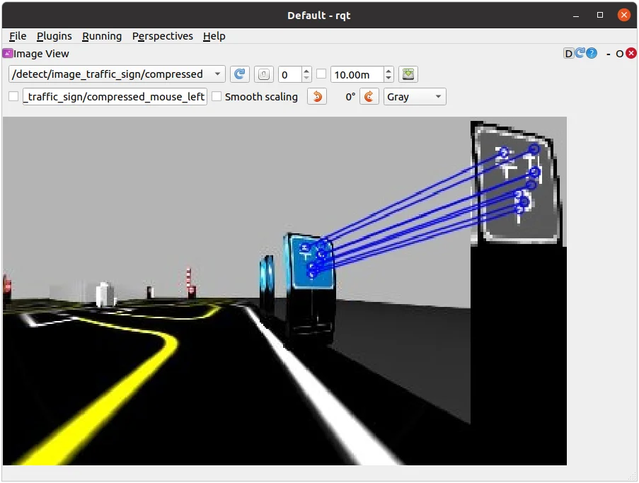
Create a new image view window and select the topic: /detect/image_traffic_sign/compressed
This will display the result of traffic sign detection in real-time. The detected traffic sign will be overlaid on the screen based on the mission assigned.
Below are examples of successfully detected traffic signs for different missions:
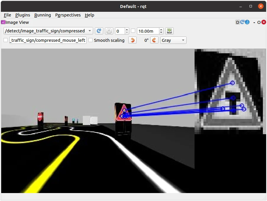


Detecting Intersection, Left, and Right signs (mission:=intersection)
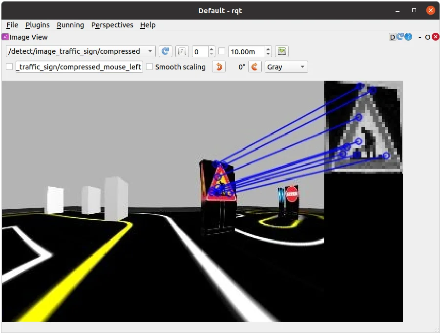
Detecting Construction, and Parking signs (mission:=construction, mission:=parking)


Detecting the Tunnel, and Level Crossing signs (mission:=level_crossing, mission:=tunnel)
Missions
AutoRace is a competition for autonomous driving robot platforms designed to provide varied test conditions for autonomous robotics development. The provided open source libraries are based on ROS and are intended to be used as a base for further competitor development. Join Autorace and show off your development skill! WARNING: Be sure to read Autonomous Driving in order to start missions.
Traffic Lights
This section describes how to complete the traffic light mission by having TurtleBot3 recognize the traffic lights and complete the course.
Traffic Lights detection process
- Filter the image to extract the red, yellow, green color mask images.
- Locate the circle in the region of interest(RoI) for each masked image.
- Find the red, yellow, and green traffic lights in that order.
Traffic Lights Detection
- Open a new terminal and launch Autorace Gazebo simulation.
$ ros2 launch turtlebot3_gazebo turtlebot3_autorace_2020.launch.py
- Open a new terminal and launch the intrinsic calibration node.
$ ros2 launch turtlebot3_autorace_camera intrinsic_camera_calibration.launch.py
- Open a new terminal and launch the extrinsic calibration node.
$ ros2 launch turtlebot3_autorace_camera extrinsic_camera_calibration.launch.py
- Open a new terminal and launch the traffic light detection node with a calibration option.
$ ros2 launch turtlebot3_autorace_detect detect_traffic_light.launch.py calibration_mode:=True
- Execute rqt on
Remote PC.
$ rqt
-
Navigate to Plugins > Visualization > Image view. Create two image view windows.
-
In one window, select the
/detect/image_traffic_light/compressedtopic. In another window, select one of the four topics to view the masked images:
/detect/image_red_light,/detect/image_yellow_light,/detect/image_green_light,/detect/image_traffic_light.
Detecting the Yellow light. The image on the right displays
/detect/image_yellow_lighttopic.
Detecting the Yellow light. The image on the right displays
/detect/image_yellow_lighttopic.
Detecting the Red light. The image on the right displays
/detect/image_red_lighttopic. -
Navigate to Plugins > Configuration > Dynamic Reconfigure.
-
Adjust the parameters in
/detect/traffic_lightto adjust the configuration of each masked image topic.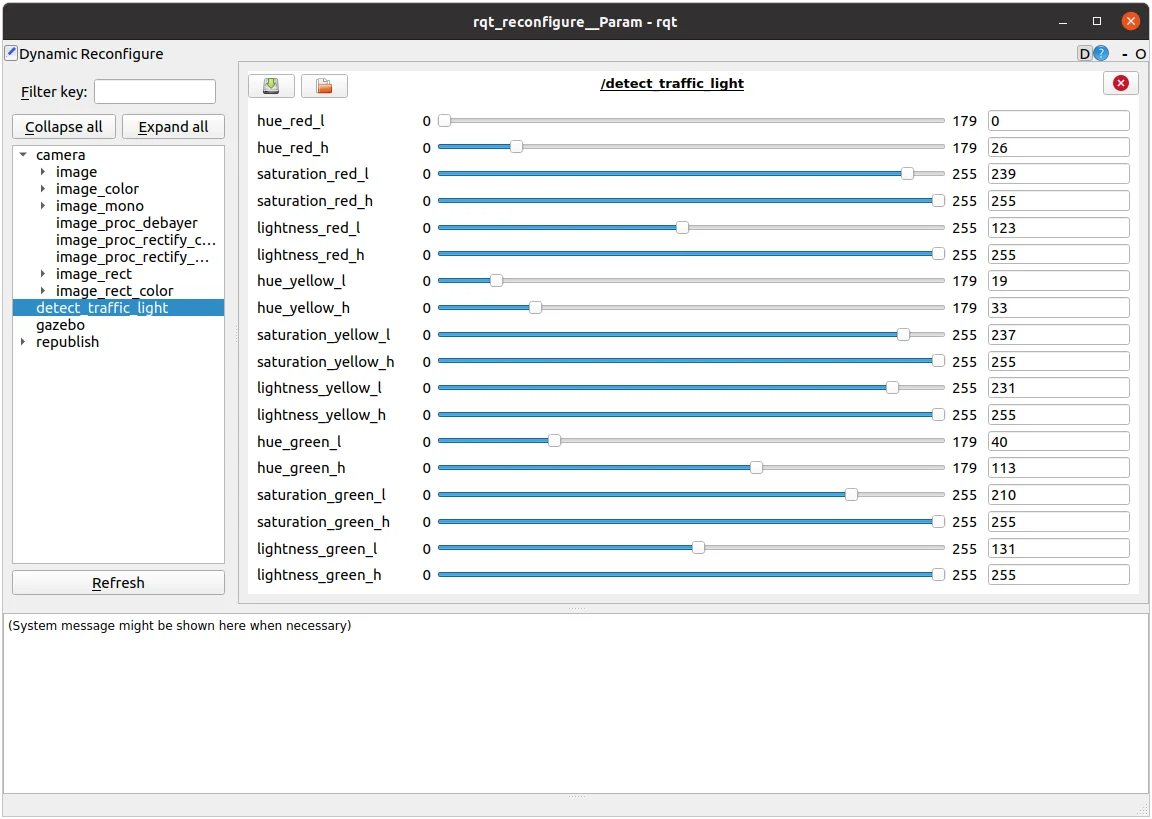
Traffic light reconfigure
Saving Calibration Data
- Open the
traffic_light.yamlfile located at turtlebot3_autorace_detect/param/traffic_light/.
$ gedit ~/turtlebot3_ws/src/turtlebot3_autorace_2020/turtlebot3_autorace_detect/param/traffic_light/traffic_light.yaml
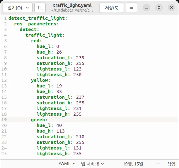
turtlebot3_autorace_detect/param/traffic_light/'traffic_light.yaml'
- Write the modified values and save the file to keep your changes.
Testing Traffic Light Detection
-
Close all terminals or terminate them with
Ctrl+C -
Open a new terminal and launch Autorace Gazebo simulation.
$ ros2 launch turtlebot3_gazebo turtlebot3_autorace_2020.launch.py
- Open a new terminal and launch the intrinsic calibration node.
$ ros2 launch turtlebot3_autorace_camera intrinsic_camera_calibration.launch.py
- Open a new terminal and launch the extrinsic calibration node.
$ ros2 launch turtlebot3_autorace_camera extrinsic_camera_calibration.launch.py
- Open a new terminal and launch the traffic light detection node.
$ ros2 launch turtlebot3_autorace_detect detect_traffic_light.launch.py
- Open a new terminal and execute the rqt_image_view.
$ rqt
- Check each topics:
/detect/image_red_light,/detect/image_yellow_light,/detect/image_green_light.
Intersection
This mission does not have any associated example code.
Construction
This section describes how to complete the construction mission. If the TurtleBot encounters an object while following a lane, it will swerve into the opposite lane to avoid the object before returning to its original lane.
Construction avoidance process
-
The TurtleBot is following a lane and it determines that there may be an obstacle in its path.
-
If an obstacle is detected within the danger zone, Turtlebot swerves to the opposite lane to avoid the obstacle.
-
The TurtleBot returns to it's original lane again and continues following it.
How to Run Construction Mission
-
Close all terminals or terminate them with
Ctrl+C -
Open a new terminal and launch the Autorace Gazebo simulation.
$ ros2 launch turtlebot3_gazebo turtlebot3_autorace_2020.launch.py
- Open a new terminal and launch the intrinsic calibration node.
$ ros2 launch turtlebot3_autorace_camera intrinsic_camera_calibration.launch.py
- Open a new terminal and launch the extrinsic calibration node.
$ ros2 launch turtlebot3_autorace_camera extrinsic_camera_calibration.launch.py
- Open a new terminal and launch the construction mission node.
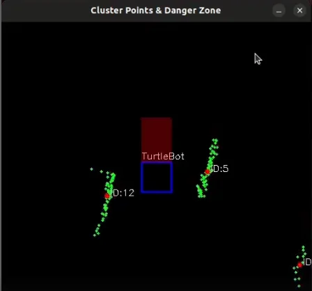
$ ros2 launch turtlebot3_autorace_mission mission_construction.launch.py
- On the image window, you can watch the LiDAR visualization. The detected lidar points, and danger zone are displayed.
Parking
This mission does not have any associated example code.
Level Crossing
This section describes how you can detect a traffic bar. TurtleBot should detect the stop sign and wait for the crossing gate to open.
Level Crossing detection process
- Filter the image to extract the red color mask image.
- Find the rectangle in the masked image.
- Connect the three squares to make a straight line.
- Determine whether the bar is open or closed by measuring the slope of the line.
Level Crossing Detection
-
Close all terminals or terminate them with
Ctrl+C -
Open a new terminal and launch Autorace Gazebo simulation.
$ ros2 launch turtlebot3_gazebo turtlebot3_autorace_2020.launch.py
- Open a new terminal and launch the intrinsic calibration node.
$ ros2 launch turtlebot3_autorace_camera intrinsic_camera_calibration.launch.py
- Open a new terminal and launch the extrinsic calibration node.
$ ros2 launch turtlebot3_autorace_camera extrinsic_camera_calibration.launch.py
- Open a new terminal and launch the level crossing detection node with a calibration option.
$ ros2 launch turtlebot3_autorace_detect detect_level_crossing.launch.py calibration_mode:=True
- Open a new terminal and execute rqt.
$ rqt
-
Select two topics on Image View Plugin:
/detect/image_level_color_filtered/compressed,/detect/image_level/compressed.
-
Adjust parameters in the
detect_level_crossingon Dynamic Reconfigure Plugin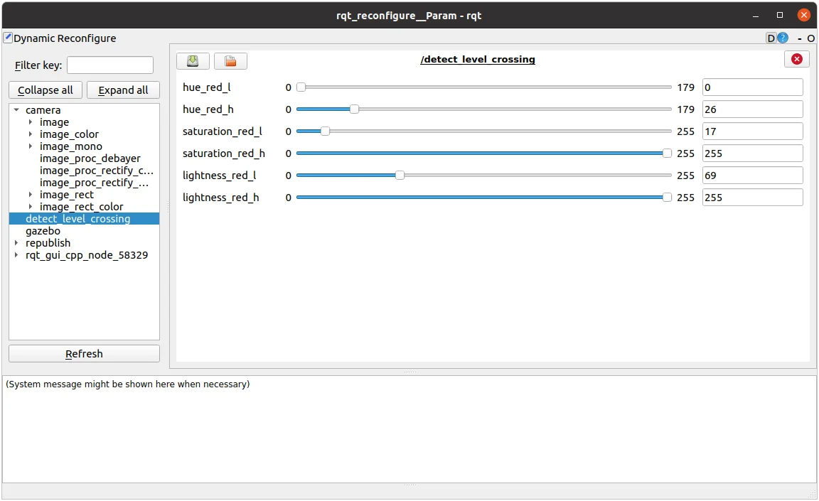
-
Open
level.yamlfile located at turtlebot3_autorace_detect/param/level/.
$ gedit ~/turtlebot3_ws/src/turtlebot3_autorace/turtlebot3_autorace_detect/param/level/level.yaml
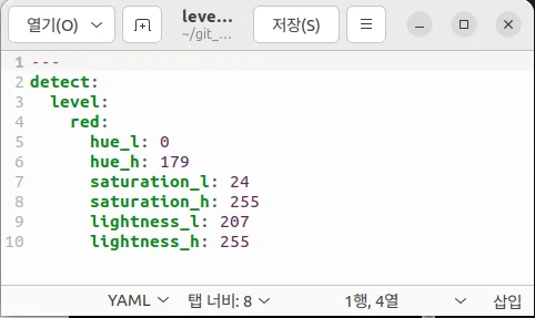
- Write modified values to the file and save.
Testing Level Crossing Detection
-
Close all terminals or terminate them with
Ctrl+C -
Open a new terminal and launch Autorace Gazebo simulation.
$ ros2 launch turtlebot3_gazebo turtlebot3_autorace_2020.launch.py
- Open a new terminal and launch the intrinsic calibration node.
$ ros2 launch turtlebot3_autorace_camera intrinsic_camera_calibration.launch.py
- Open a new terminal and launch the extrinsic calibration node.
$ ros2 launch turtlebot3_autorace_camera extrinsic_camera_calibration.launch.py
- Open a new terminal and launch the level crossing detection node.
$ ros2 launch turtlebot3_autorace_detect detect_level_crossing.launch.py
- Open a new terminal and execute the rqt_image_view.
$ rqt
- Check the image topic:
/detect/image_level/compressedon Image View Plugin.
Tunnel
This section describes how to complete the tunnel mission. The TurtleBot must use maps and navigation to proceed through obstacle areas with no lanes.
How to Run Tunnel Mission
NOTE: Change the navigation parameters in the turtlebot3/turtlebot3_navigation2/param/buger_cam file. If you slam and make a new map, Place the new map in the turtlebot3_autorace package at /turtlebot3_autorace/turtlebot3_autorace_tunnel/map/.
-
Close all terminals or terminate them with
Ctrl+C -
Open a new terminal and launch the Autorace Gazebo simulation.
$ ros2 launch turtlebot3_gazebo turtlebot3_autorace_2020.launch.py
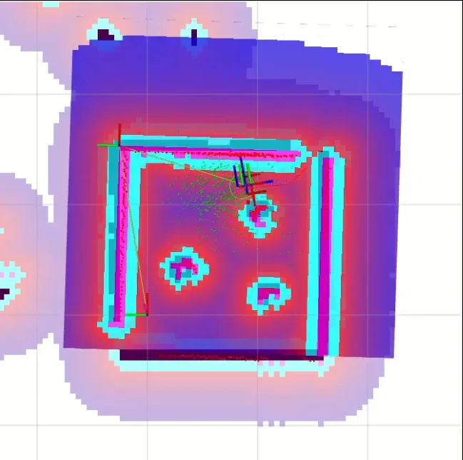
- Open a new terminal and launch the tunnel mission node. This node runs the navigation and specifies the initial and target locations.
$ ros2 launch turtlebot3_autorace_mission mission_tunnel.launch.py
- On the Rviz2 screen, you can watch the TurtleBot generate and follow a path in real-time.
Set Initial Position and Goal Position
You can modify the initial position and goal position to fit your plan.
- Open the
navigation.yamlfile located at turtlebot3_autorace_mission/param/.
$ gedit ~/turtlebot3_ws/src/turtlebot3_autorace/turtlebot3_autorace_mission/param/navigation.yaml
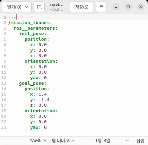
- Write modified values and save the file.
Getting Started
NOTE
- The Autorace package was developed on
Ubuntu 20.04runningROS1 Noetic Ninjemys. - The Autorace package has only been comprehensively tested for operation in the Gazebo simulator.
- Instructions for correct simulation setup are available in the Simulation section of the manual.
Tip: If you have an actual TurtleBot3, you can perform up to Lane Detection from our Autonomous Driving package with your physical robot. For more details, click the expansion note (![]() Click to expand: ) at the end of the content in each sub section.
Click to expand: ) at the end of the content in each sub section.
The contents of the e-Manual are subject to change without prior notice. Therefore, some video content may differ from the content in the e-Manual.
Prerequisites
Remote PC
- ROS 1 Noetic installed on your Laptop or desktop PC.
- These instructions are intended for use in a Gazebo simulation, but can be ported to the actual robot later.
 Click to expand : Prerequisites for use of actual TurtleBot3
What you need for Autonomous Driving
TurtleBot3 Burger
- The basic model for AutoRace packages for autonomous driving on ROS.
- Provided source code and AutoRace Packages are made based on the TurtleBot3 Burger.
Remote PC
- Communicates with the single board computer (SBC) on the Turtlebot3.
- Laptop, desktop, or other device running ROS 1.
Raspberry Pi camera module with a camera mount
- You can use a different module if ROS supports it.
- Source code provided to calibrate the camera was created for the (Fisheye Lens) module.
AutoRace tracks and objects
- Download 3D CAD files for AutoRace tracks, Traffic signs, traffic lights and other objects at ROBOTIS_GIT/autorace.
- Download a referee system at ROBOTIS-GIT/autorace_referee
Install Autorace Packages
- Install the AutoRace 2020 meta package on the
Remote PC.
$ cd ~/catkin_ws/src/
$ git clone -b noetic https://github.com/ROBOTIS-GIT/turtlebot3_autorace_2020.git
$ cd ~/catkin_ws && catkin_make
- Install additional required packages on the
Remote PC.
$ sudo apt install ros-noetic-image-transport ros-noetic-cv-bridge ros-noetic-vision-opencv python3-opencv libopencv-dev ros-noetic-image-proc
Click to expand : Autorace Package Installation for an actual TurtleBot3
The following instructions describes how to install packages and to calibrate the camera for an actual TurtleBot3.
- Install AutoRace packages on both the
Remote PCandSBC.
$ cd ~/catkin_ws/src/
$ git clone -b noetic https://github.com/ROBOTIS-GIT/turtlebot3_autorace_2020.git
$ cd ~/catkin_ws && catkin_make
-
Install additional required packages on the
SBC.-
Create a swap file to prevent lack of memory when building OpenCV.
$ sudo fallocate -l 4G /swapfile$ sudo chmod 600 /swapfile$ sudo mkswap /swapfile$ sudo swapon /swapfile -
Install required dependencies.
$ sudo apt-get update$ sudo apt-get install build-essential cmake gcc g++ git unzip pkg-config$ sudo apt-get install libjpeg-dev libpng-dev libtiff-dev libavcodec-dev libavformat-dev libswscale-dev libgtk2.0-dev libcanberra-gtk* libxvidcore-dev libx264-dev python3-dev python3-numpy python3-pip libtbb2 libtbb-dev libdc1394-22-dev libv4l-dev v4l-utils libopenblas-dev libatlas-base-dev libblas-dev liblapack-dev gfortran libhdf5-dev libprotobuf-dev libgoogle-glog-dev libgflags-dev protobuf-compiler
-
Build with opencv & opencv_contrib
$ cd ~$ wget -O opencv.zip https://github.com/opencv/opencv/archive/4.5.0.zip$ wget -O opencv_contrib.zip https://github.com/opencv/opencv_contrib/archive/4.5.0.zip$ unzip opencv.zip$ unzip opencv_contrib.zip$ mv opencv-4.5.0 opencv$ mv opencv_contrib-4.5.0 opencv_contrib -
Create cmake file.
$ cd opencv$ mkdir build$ cd build$ cmake -D CMAKE_BUILD_TYPE=RELEASE \-D CMAKE_INSTALL_PREFIX=/usr/local \-D OPENCV_EXTRA_MODULES_PATH=~/opencv_contrib/modules \-D ENABLE_NEON=ON \-D BUILD_TIFF=ON \-D WITH_FFMPEG=ON \-D WITH_GSTREAMER=ON \-D WITH_TBB=ON \-D BUILD_TBB=ON \-D BUILD_TESTS=OFF \-D WITH_EIGEN=OFF \-D WITH_V4L=ON \-D WITH_LIBV4L=ON \-D WITH_VTK=OFF \-D OPENCV_ENABLE_NONFREE=ON \-D INSTALL_C_EXAMPLES=OFF \-D INSTALL_PYTHON_EXAMPLES=OFF \-D BUILD_NEW_PYTHON_SUPPORT=ON \-D BUILD_opencv_python3=TRUE \-D OPENCV_GENERATE_PKGCONFIG=ON \-D BUILD_EXAMPLES=OFF .. -
It will take an hour or two to build.
$ cd ~/opencv/build$ make -j4$ sudo make install$ sudo ldconfig$ make clean$ sudo apt-get update -
Turn off the Raspberry Pi, take out the microSD card and edit the config.txt in the system-boot section. add start_x=1 before the enable_uart=1 line.
$ sudo apt install ffmpeg$ ffmpeg -f video4linux2 -s 640x480 -i /dev/video0 -ss 0:0:2 -frames 1 capture_test.jpg -
Install additional required packages
$ sudo apt install ros-noetic-cv-camera
-
-
Install additional required packages on
Remote PC.
$ sudo apt install ros-noetic-image-transport ros-noetic-image-transport-plugins ros-noetic-cv-bridge ros-noetic-vision-opencv python3-opencv libopencv-dev ros-noetic-image-proc ros-noetic-cv-camera ros-noetic-camera-calibration
Camera Calibration
Calibrating the camera is very important for autonomous driving. The following instructions provide a step by step guide on how to calibrate the camera. The following instructions provide a step by step guide on how to calibrate the camera.
Camera Imaging Calibration
Camera image calibration is not required in Gazebo Simulation.
Click to expand : Camera Imaging Calibration with an actual TurtleBot3
- Launch roscore on
Remote PC.
$ roscore
- Trigger the camera on
SBC.
$ roslaunch turtlebot3_autorace_camera raspberry_pi_camera_publish.launch
- Execute rqt_image_view on
Remote PC.
$ rqt_image_view
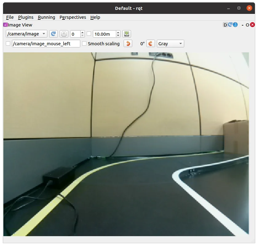
rqt_image view
Intrinsic Camera Calibration
Intrinsic Camera Calibration is not required in Gazebo simulation.
Click to expand : Intrinsic Camera Calibration with an actual TurtleBot3
Print a checkerboard on A4 size paper. The checkerboard is used for Intrinsic Camera Calibration.
-
The checkerboard is stored at turtlebot3_autorace_camera/data/checkerboard_for_calibration.pdf
-
Modify value of parameters in turtlebot3_autorace_camera/launch/intrinsic_camera_calibration.launch
-
For detailed information on the camera calibration, see Camera Calibration manual from ROS Wiki.

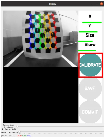
Checkerboard
- Launch roscore on
Remote PC.
$ roscore
- Trigger the camera on
SBC.
$ roslaunch turtlebot3_autorace_camera raspberry_pi_camera_publish.launch
- Run a intrinsic camera calibration launch file on
Remote PC.
$ roslaunch turtlebot3_autorace_camera intrinsic_camera_calibration.launch mode:=calibration
-
Use the checkerboard to calibrate the camera, and click CALIBRATE.
-
Click Save to save the intrinsic calibration data.
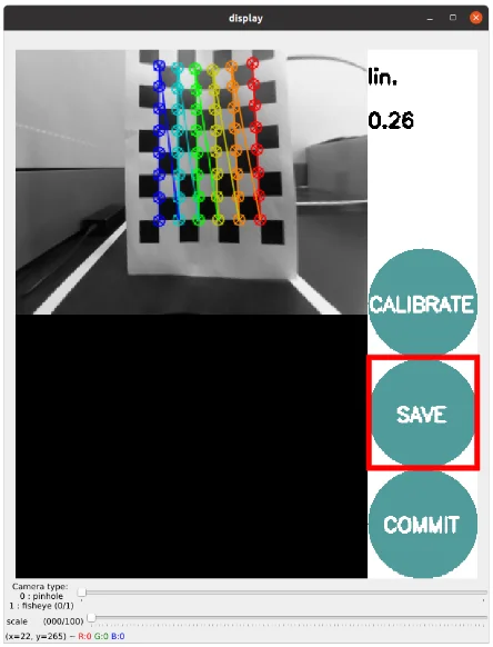
-
calibrationdata.tar.gz folder will be created at /tmp folder.

-
Extract calibrationdata.tar.gz folder, and open ost.yaml.

ost.yaml
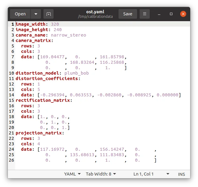
Intrinsic Calibration Data in ost.yaml
-
Copy and paste the data from ost.yaml to camerav2_320x240_30fps.yaml.

camerav2_320x240_30fps.yaml
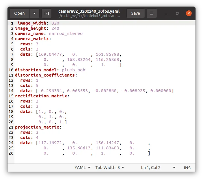
Intrinsic Calibration Data in camerav2_320x240_30fps.yaml
Extrinsic Camera Calibration
- Open a new terminal on the
Remote PCand launch Gazebo.
$ roslaunch turtlebot3_gazebo turtlebot3_autorace_2020.launch
- Open a new terminal and launch the intrinsic camera calibration node.
$ roslaunch turtlebot3_autorace_camera intrinsic_camera_calibration.launch
- Open a new terminal and launch the extrinsic camera calibration node.
$ roslaunch turtlebot3_autorace_camera extrinsic_camera_calibration.launch mode:=calibration
- Execute rqt on the
Remote PC.
$ rqt
-
Select plugins > visualization > Image view. Create two image view windows.
-
Select the
/camera/image_extrinsic_calib/compressedtopic in one window and/camera/image_projected_compensatedin the other.-
The first topic shows an image with a red trapezoidal shape and the latter shows the ground projected view (Bird's eye view).
/camera/image_extrinsic_calib/compressed(Left) and/camera/image_projected_compensated(Right)
-
-
Excute rqt_reconfigure on
Remote PC.
$ rosrun rqt_reconfigure rqt_reconfigure
-
Adjust parameters in
/camera/image_projectionand/camera/image_compensation_projectionto calibrate the image.-
Changing
/camera/image_projectionaffects the/camera/image_extrinsic_calib/compressedtopic. -
Intrinsic camera calibration modifies the perspective of the image in the red trapezoid.
rqt_reconfigure
-
-
After that, overwrite the updated values to the yaml files in turtlebot3_autorace_camera/calibration/extrinsic_calibration/. This will save the current calibration parameters so that they can be loaded later.
turtlebot3_autorace_camera/calibration/extrinsic_calibration/
compensation.yaml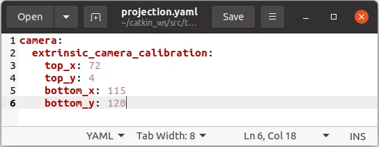
turtlebot3_autorace_camera/calibration/extrinsic_calibration/
projection.yaml
Click to expand : Extrinsic Camera Calibration with an actual TurtleBot3
- Launch roscore on the
Remote PC.
$ roscore
- Trigger the camera on the
SBC.
$ roslaunch turtlebot3_autorace_camera raspberry_pi_camera_publish.launch
- Use the command on the
Remote PC.
$ roslaunch turtlebot3_autorace_camera intrinsic_camera_calibration.launch mode:=action
- Run the extrinsic camera calibration launch file on the
Remote PC.
$ roslaunch turtlebot3_autorace_camera extrinsic_camera_calibration.launch mode:=calibration
- Execute rqt on the
Remote PC.
$ rqt
-
Click plugins > visualization > Image view; Multiple windows will be present.
-
Select
/camera/image_extrinsic_calib/compressedand/camera/image_projected_compensatedtopics to display in the two monitors.
-
One of two screens will show an image with a red rectangular box. The other one shows the ground projected view (Bird's eye view).
/camera/image_extrinsic_calib/compressedtopic/camera/image_projected_compensatedtopic
- Excute rqt_reconfigure on the
Remote PC.
$ rosrun rqt_reconfigure rqt_reconfigure
- Adjust parameters in
/camera/image_projectionand/camera/image_compensation_projection.
-
Changing the
/camera/image_projectionparameter will alter the/camera/image_extrinsic_calib/compressedtopic. -
Intrinsic camera calibration will transform the image surrounded by the red rectangle, and will show the image that looks from over the lane.
rqt_reconfigure
Result from parameter modification.
Check Calibration Result
After completing calibration, follow the step by step instructions below on the Remote PC to check the calibration result.
-
Close all terminals.
-
Open a new terminal and launch Autorace Gazebo simulation. Launch
roscorewith the roslaunch command.
$ roslaunch turtlebot3_gazebo turtlebot3_autorace_2020.launch
- Open a new terminal and launch the intrinsic calibration node.
$ roslaunch turtlebot3_autorace_camera intrinsic_camera_calibration.launch
- Open a new terminal and launch the extrinsic calibration node.
$ roslaunch turtlebot3_autorace_camera extrinsic_camera_calibration.launch
- Open a new terminal and launch the rqt image viewer.
$ rqt_image_view
- With successful calibration settings, the bird eye view image should appear like the image below when the
/camera/image_projected_compensatedtopic is selected.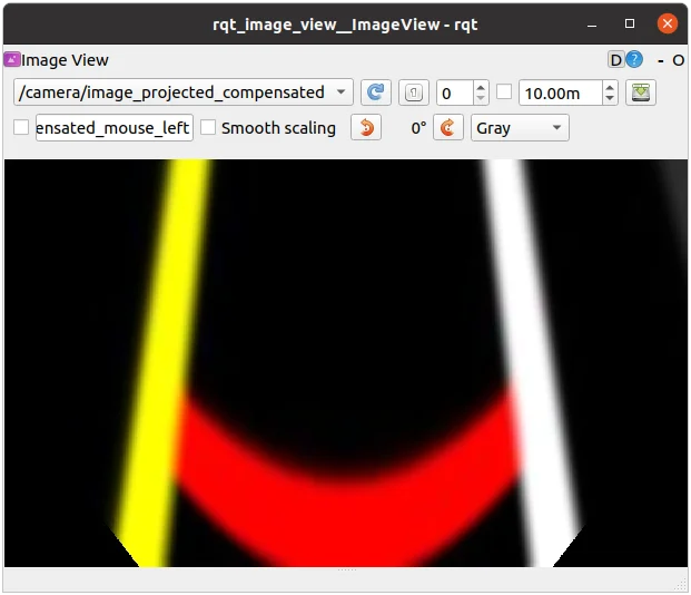
Click to expand : Extrinsic Camera Calibration for use of actual TurtleBot3
When you complete all the camera calibration (Camera Imaging Calibration, Intrinsic Calibration, Extrinsic Calibration), be sure that the calibration is successfully applied to the camera.
The following instruction describes settings for recognition.
- Launch roscore on
Remote PC.
$ roscore
- Trigger the camera on
SBC.
$ roslaunch turtlebot3_autorace_camera raspberry_pi_camera_publish.launch
- Run a intrinsic camera calibration launch file on
Remote PC.
$ roslaunch turtlebot3_autorace_camera intrinsic_camera_calibration.launch mode:=action
- Open terminal and use the command on
Remote PC.
$ roslaunch turtlebot3_autorace_camera extrinsic_camera_calibration.launch mode:=action
- Execute rqt on
Remote PC.
$ rqt
rqt_reconfigure
From now, the following descriptions will mainly adjust feature detector / color filter for object recognition. Every adjustment after here is independent to each other process. However, if you want to adjust each parameters in series, complete each individual adjustment, then continue to next.
Lane Detection
The Lane detection package that runs on the Remote PC receives camera images either from TurtleBot3 or Gazebo simulation to detect driving lanes and to drive the Turtlebot3 along them.
The following instructions describe how to use and calibrate the lane detection feature via rqt.
-
Place the TurtleBot3 between yellow and white lanes.
NOTE: The lane detection filters yellow on the left side and white on the right side. Be sure that the yellow lane is on the left side of the robot.
-
Open a new terminal and launch the Autorace Gazebo simulation. Launch
roscorewith the roslaunch command.
$ roslaunch turtlebot3_gazebo turtlebot3_autorace_2020.launch
- Open a new terminal and launch the intrinsic calibration node.
$ roslaunch turtlebot3_autorace_camera intrinsic_camera_calibration.launch
- Open a new terminal and launch the extrinsic calibration node.
$ roslaunch turtlebot3_autorace_camera extrinsic_camera_calibration.launch
- Open a new terminal and launch the lane detection calibration node.
$ roslaunch turtlebot3_autorace_detect detect_lane.launch mode:=calibration
- Open a new terminal and launch the rqt.
$ rqt
-
Launch the rqt image viewer by selecting Plugins > Cisualization > Image view.
Multiple rqt plugins can be run. -
Display three topics at each image viewer
/detect/image_lane/compressed
/detect/image_yellow_lane_marker/compressed: a yellow range color filtered image.
/detect/image_white_lane_marker/compressed: a white range color filtered image.
- Open a new terminal and execute rqt_reconfigure.
$ rosrun rqt_reconfigure rqt_reconfigure
-
Click detect_lane then adjust parameters so that yellow and white colors can be filtered properly.
TIP: Calibration for line color filtering is sometimes difficult due to the surrounding physical environment, such as the luminance of light in the room etc.
To get started quickly, use the values from the lane.yaml file located in turtlebot3_auatorace_detect/param/lane/ as the reconfiguration parameters, then start calibration.
Calibrate hue low - high value at first. (1) Hue value means the color, and every color, likeyellowandwhitehave their own region of hue values (refer to a hsv map for more information).
Then calibrate the saturation low - high value. (2) Every color also has their own field of saturation.
Finally, calibrate the lightness low - high value. (3) The provided source code has an auto-adjustment function, so calibrating lightness low value is not required. You can set the lightness high value to 255.
Clearly filtered line images will give you clear results for lane tracking. -
Open lane.yaml file located in turtlebot3_autorace_detect/param/lane/. Writing modified values to this file will allow the camera to load the set parameters on future launches.
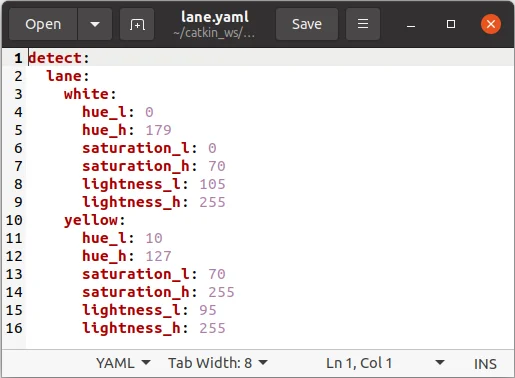
Modified lane.yaml file
-
Close the rqt_reconfigure and detect_lane terminals.
-
Open a new terminal and launch the lane detect node without the calibration option.
$ roslaunch turtlebot3_autorace_detect detect_lane.launch
- Open a new terminal and launch the node below to start the lane following operation.
$ roslaunch turtlebot3_autorace_driving turtlebot3_autorace_control_lane.launch
Click to expand : How to Perform Lane Detection with Actual TurtleBot3?
Lane detection package allows Turtlebot3 to automatically drive between two lanes without external influence.
The following instructions describe how to use the lane detection feature and to calibrate camera via rqt.
-
Place TurtleBot3 between yellow and white lanes.
NOTE: Be sure that yellow lane is placed left side of the robot and White lane is placed right side of the robot.
-
Launch roscore on the
Remote PC.
$ roscore
- Trigger the camera on the
SBC.
$ roslaunch turtlebot3_autorace_camera raspberry_pi_camera_publish.launch
- Run a intrinsic camera calibration launch file on the
Remote PC.
$ roslaunch turtlebot3_autorace_camera intrinsic_camera_calibration.launch mode:=action
- Run a extrinsic camera calibration launch file on the
Remote PC.
$ roslaunch turtlebot3_autorace_camera extrinsic_camera_calibration.launch mode:=action
- Run a lane detection launch file on the
Remote PC
$ roslaunch turtlebot3_autorace_detect detect_lane.launch mode:=calibration
- Execute rqt on the
Remote PC.
$ rqt
-
Click plugins > visualization > Image view; Multiple windows will be present.
-
Select three topics at each image view:
/detect/image_yellow_lane_marker/compressed,/detect/image_lane/compressed,/detect/image_white_lane_marker/compressed- Left (Yellow line) and Right (White line) screen show a filtered image. Center screen is the view of the camera from TurtleBot3.
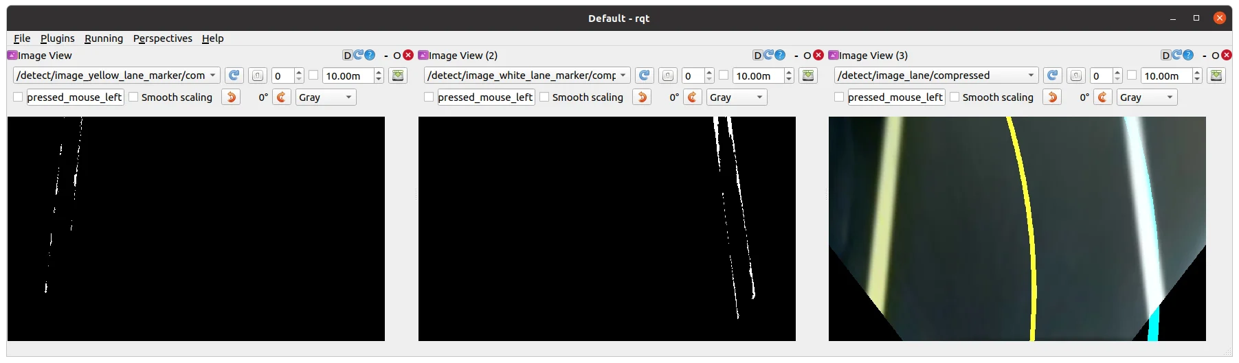
Image view of
/detect/image_yellow_lane_marker/compressedtopic ,/detect/image_white_lane_marker/compressedtopic ,/detect/image_lane/compressedtopic
- Left (Yellow line) and Right (White line) screen show a filtered image. Center screen is the view of the camera from TurtleBot3.
-
Execute rqt_reconfigure on
Remote PC.
$ rosrun rqt_reconfigure rqt_reconfigure
-
Click Detect Lane then adjust parameters to do line color filtering.
List of Detect Lane Parameters
Filtered Image after adjusting parameters at rqt_reconfigure
TIP: Calibration for line color filtering is sometimes difficult due to the surrounding physical environment, such as the luminance of light in the room etc.
To get started quickly, use the values from the lane.yaml file located in turtlebot3_auatorace_detect/param/lane/ as the reconfiguration parameters, then start calibration.
Calibrate hue low - high value at first. (1) Hue value means the color, and every color, likeyellowandwhitehave their own region of hue values (refer to a hsv map for more information).
Then calibrate the saturation low - high value. (2) Every color also has their own field of saturation.
Finally, calibrate the lightness low - high value. (3) The provided source code has an auto-adjustment function, so calibrating lightness low value is not required. You can set the lightness high value to 255.
Clearly filtered line images will give you clear results for lane tracking. -
Open lane.yaml file located in turtlebot3_autorace_detect/param/lane/. Writing modified values to this file will allow the camera to load the set parameters on future launches.
-
Close both rqt_rconfigure and turtlebot3_autorace_detect_lane.
-
Open a terminal and on the
Remote PC.
$ roslaunch turtlebot3_autorace_detect detect_lane.launch mode:=action
-
Check if the results come out correctly.
- Open terminal on the
Remote PC.
$ roslaunch turtlebot3_autorace_driving turtlebot3_autorace_control_lane.launch- Open terminal on the
Remote PC.
$ roslaunch turtlebot3_bringup turtlebot3_robot.launch - Open terminal on the
-
After using the commands, TurtleBot3 will start to run.
Traffic Sign Detection
TurtleBot3 can detect various signs with the SIFT algorithm to compare the source image and the camera image, and perform programmed tasks while it drives.
Follow the instructions below to test the traffic sign detection.
NOTE: More edges in the traffic sign increase recognition results from the SIFT algorithm.
Please refer to the SIFT documentation for more information.
- Open a new terminal and launch the Autorace Gazebo simulation. Launch
roscorewith the roslaunch command.
$ roslaunch turtlebot3_gazebo turtlebot3_autorace_2020.launch
- Open a new terminal and launch the teleoperation node. Drive the TurtleBot3 along the lane and stop where traffic signs can be clearly seen by the camera.
$ roslaunch turtlebot3_teleop turtlebot3_teleop_key.launch
- Open a new terminal and launch the rqt_image_view.
$ rqt_image_view
-
Select the
/camera/image_compensatedtopic to display the camera image. -
Capture each traffic sign from the
rqt_image_viewand crop unnecessary part of image. For the best performance, it is recommended to use original traffic sign images as seen on the track. -
Save the images in the turtlebot3_autorace_detect package /turtlebot3_autorace_2020/turtlebot3_autorace_detect/image/. The file name should match with the name used in the source code.
construction.png,intersection.png,left.png,right.png,parking.png,stop.png,tunnel.pngfile names are used by default.
- Open a new terminal and launch the intrinsic calibration node.
$ roslaunch turtlebot3_autorace_camera intrinsic_camera_calibration.launch
- Open a new terminal and launch the extrinsic calibration node.
$ roslaunch turtlebot3_autorace_camera extrinsic_camera_calibration.launch
- Open a new terminal and launch the traffic sign detection node.
A specific mission for the mission argument must be selected from the following options.
intersection,construction,parking,level_crossing,tunnel
$ roslaunch turtlebot3_autorace_detect detect_sign.launch mission:=SELECT_MISSION
- Open a new terminal and launch the rqt image view plugin.
$ rqt_image_view
-
Select
/detect/image_traffic_sign/compressedtopic from the drop down list. A screen will display the result of traffic sign detection.
Detecting the Intersection sign when
mission:=intersection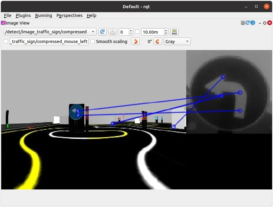
Detecting the Left sign when
mission:=intersection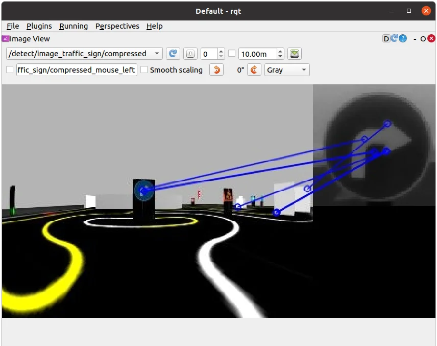
Detecting the Right sign when
mission:=intersection
Detecting the Construction sign when
mission:=construction
Detecting the Parking sign when
mission:=parking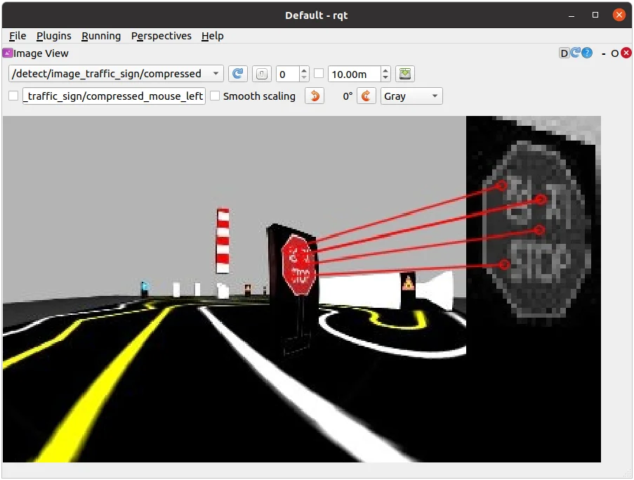
Detecting the Level Crossing sign when
mission:=level_crossing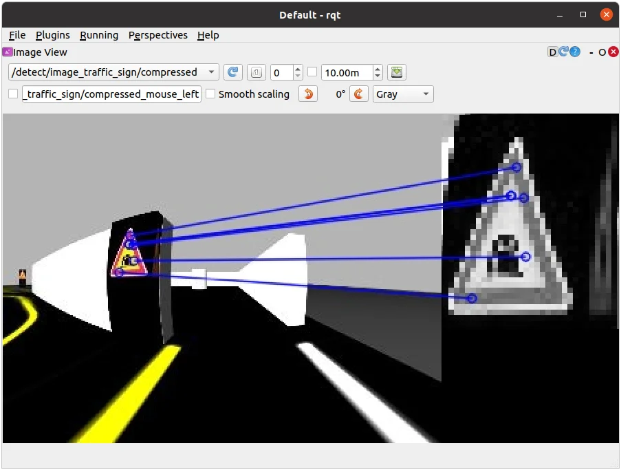
Detecting the Tunnel sign when
mission:=tunnel
Missions
AutoRace is a competition for autonomous driving robot platforms designed to provide varied test conditions for autonomous robotics development. The provided open source libraries are based on ROS and are intended to be used as a base for further competitor development. Join Autorace and show off your development skill! WARNING: Be sure to read Autonomous Driving in order to start missions.
Traffic Lights
Traffic Light is the first mission of AutoRace. TurtleBot3 must recognize the traffic lights and start the course.
Traffic Lights Detection
NOTE: In order to fix the traffic light to a specific color in Gazebo, you may modify the controlMission method in the core_node_mission file in the turtlebot3_autorace_2020/turtlebot3_autorace_core/nodes/ directory.
- Open a new terminal and launch Autorace Gazebo simulation. Launch
roscorewith the roslaunch command.
$ roslaunch turtlebot3_gazebo turtlebot3_autorace_2020.launch
- Open a new terminal and launch the intrinsic calibration node.
$ roslaunch turtlebot3_autorace_camera intrinsic_camera_calibration.launch
- Open a new terminal and launch the extrinsic calibration node.
$ roslaunch turtlebot3_autorace_camera extrinsic_camera_calibration.launch
- Open a new terminal and launch the traffic light detection node with the calibration option.
$ roslaunch turtlebot3_autorace_detect detect_traffic_light.launch mode:=calibration
- Open a new terminal to execute the rqt. Open four
rqt_image_viewplugins.
$ rqt
-
Select four topics:
/detect/image_red_light,/detect/image_yellow_light,/detect/image_green_light,/detect/image_traffic_light.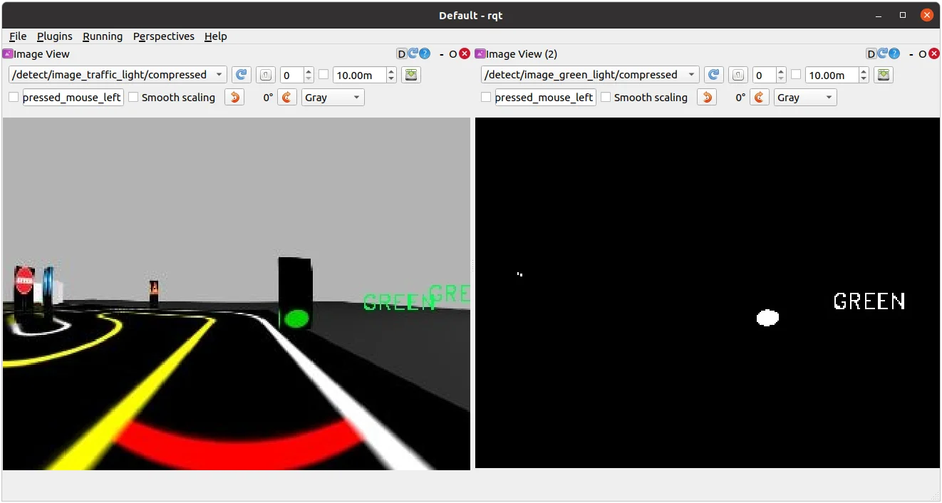
Detecting the Green light. The image on the right displays
/detect/image_green_lighttopic.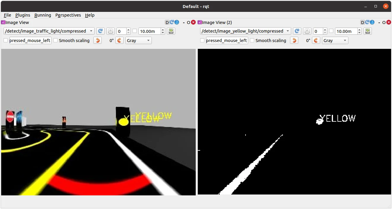
Detecting the Yellow light. The image on the right displays
/detect/image_yellow_lighttopic.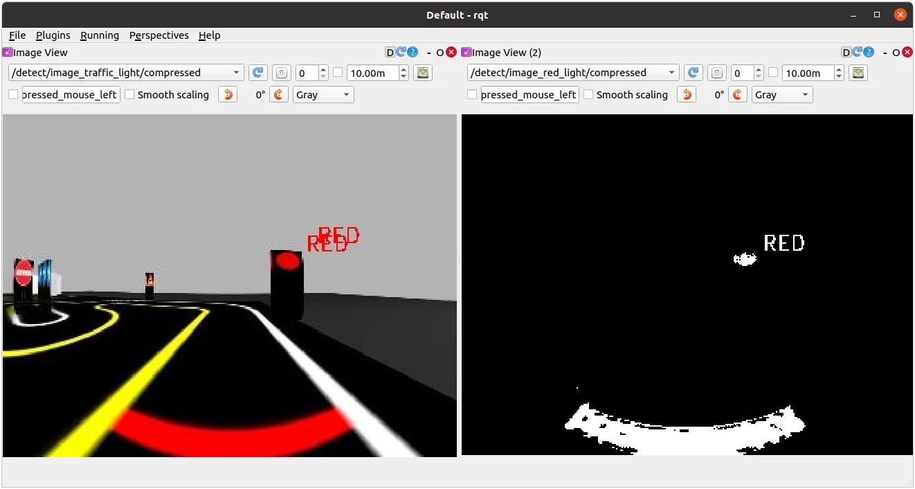
Detecting the Red light. The image on the right displays
/detect/image_red_lighttopic. -
Open a new terminal and excute rqt_reconfigure.
$ rosrun rqt_reconfigure rqt_reconfigure
-
Select
detect_traffic_lightin the left column and adjust parameters properly so that the colors of the traffic light can be detected and differentiated.
Traffic light reconfigure
-
Open the
traffic_light.yamlfile located at turtlebot3_autorace_detect/param/traffic_light/.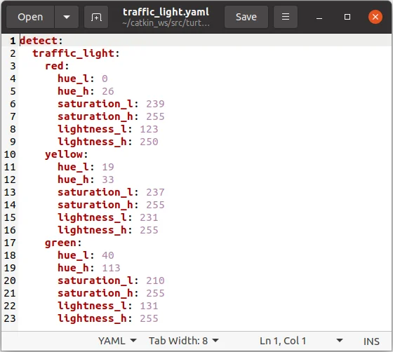
-
Write the modified values and save the file.
Testing Traffic Light Detection
-
Close all terminals or terminate them with
Ctrl+C -
Open a new terminal and launch Autorace Gazebo simulation. Launch
roscorewith the roslaunch command.
$ roslaunch turtlebot3_gazebo turtlebot3_autorace_2020.launch
- Open a new terminal and launch the intrinsic calibration node.
$ roslaunch turtlebot3_autorace_camera intrinsic_camera_calibration.launch
- Open a new terminal and launch the extrinsic calibration node.
$ roslaunch turtlebot3_autorace_camera extrinsic_camera_calibration.launch
- Open a new terminal and launch the traffic light detection node.
$ roslaunch turtlebot3_autorace_detect detect_traffic_light.launch
- Open a new terminal and execute the rqt_image_view.
$ rqt_image_view
- Check each topic:
/detect/image_red_light,/detect/image_yellow_light,/detect/image_green_light.
How to Run Traffic Light Mission
WARNING: Please calibrate the color as described in Traffic Lights Detection section before running the traffic light mission.
-
Close all terminals or terminate them with
Ctrl+C -
Open a new terminal and launch the Autorace Gazebo simulation. Launch
roscorewith the roslaunch command.
$ roslaunch turtlebot3_gazebo turtlebot3_autorace_2020.launch
- Open a new terminal and launch the intrinsic calibration node.
$ roslaunch turtlebot3_autorace_camera intrinsic_camera_calibration.launch
- Open a new terminal and launch the autorace core node with a specific mission name.
$ roslaunch turtlebot3_autorace_core turtlebot3_autorace_core.launch mission:=traffic_light
- Open a new terminal and enter the command below. This will prepare to run the traffic light mission by setting the
decided_modeto3.
$ rostopic pub -1 /core/decided_mode std_msgs/UInt8 "data: 3"
- Launch the Gazebo mission node.
$ roslaunch turtlebot3_autorace_core turtlebot3_autorace_mission.launch
Intersection
Intersection is the second mission of AutoRace. The TurtleBot3 must detect the directional sign at the intersection, and proceed to the correct path.
How to Run Intersection Mission
-
Close all terminals or terminate them with
Ctrl+C -
Open a new terminal and launch Autorace Gazebo simulation. Launch
roscorewith the roslaunch command.
$ roslaunch turtlebot3_gazebo turtlebot3_autorace_2020.launch
- Open a new terminal and launch the intrinsic calibration node.
$ roslaunch turtlebot3_autorace_camera intrinsic_camera_calibration.launch
- Open a new terminal and launch the keyboard teleoperation node.
Drive the TurtleBot3 along the lane and stop before the intersection traffic sign.
$ roslaunch turtlebot3_teleop turtlebot3_teleop_key.launch
- Open a new terminal and launch the autorace core node with a specific mission name.
$ roslaunch turtlebot3_autorace_core turtlebot3_autorace_core.launch mission:=intersection
- Open a new terminal and launch the Gazebo mission node.
$ roslaunch turtlebot3_autorace_core turtlebot3_autorace_mission.launch
- Open a new terminal and enter the command below. This will prepare to run the intersection mission by setting the
decided_modeto2.
$ rostopic pub -1 /core/decided_mode std_msgs/UInt8 "data: 2"
Construction
Construction is the third mission in TurtleBot3 AutoRace 2020. The TurtleBot3 must avoid obstacles in the construction area.
How to Run Construction Mission
-
Close all terminals or terminate them with
Ctrl+C -
Open a new terminal and launch Autorace Gazebo simulation. The
roscorewill be automatically launched with the roslaunch command.
$ roslaunch turtlebot3_gazebo turtlebot3_autorace_2020.launch
- Open a new terminal and launch the intrinsic calibration node.
$ roslaunch turtlebot3_autorace_camera intrinsic_camera_calibration.launch
- Open a new terminal and launch the keyboard teleoperation node.
Drive the TurtleBot3 along the lane and stop before the construction traffic sign.
$ roslaunch turtlebot3_teleop turtlebot3_teleop_key.launch
- Open a new terminal and launch the autorace core node with a specific mission name.
$ roslaunch turtlebot3_autorace_core turtlebot3_autorace_core.launch mission:=construction
- Open a new terminal and enter the command below. This will prepare to run the construction mission by setting the
decided_modeto2.
$ rostopic pub -1 /core/decided_mode std_msgs/UInt8 "data: 2"
Parking
Parking is the fourth mission in TurtleBot3 AutoRace 2020. The TurtleBot3 must detect the parking sign, and park in an empty parking spot.
How to Run Parking Mission
-
Close all terminals or terminate them with
Ctrl+C -
Open a new terminal and launch Autorace Gazebo simulation. The
roscorewill be automatically launched with the roslaunch command.
$ roslaunch turtlebot3_gazebo turtlebot3_autorace_2020.launch
- Open a new terminal and launch the intrinsic calibration node.
$ roslaunch turtlebot3_autorace_camera intrinsic_camera_calibration.launch
- Open a new terminal and launch the keyboard teleoperation node.
Drive the TurtleBot3 along the lane and stop before the parking traffic sign.
$ roslaunch turtlebot3_teleop turtlebot3_teleop_key.launch
- Open a new terminal and launch the autorace core node with a specific mission name.
$ roslaunch turtlebot3_autorace_core turtlebot3_autorace_core.launch mission:=parking
- Open a new terminal and launch the Gazebo mission node.
$ roslaunch turtlebot3_autorace_core turtlebot3_autorace_mission.launch
- Open a new terminal and enter the command below. This will prepare to run the parking mission by setting the
decided_modeto2.
$ rostopic pub -1 /core/decided_mode std_msgs/UInt8 "data: 2"
Level Crossing
Level Crossing is the fifth mission of TurtleBot3 AutoRace 2020. The TurtleBot3 must detect the stop sign and wait until the crossing gate is lifted.
Level Crossing Detection
-
Close all terminals or terminate them with
Ctrl+C -
Open a new terminal and launch Autorace Gazebo simulation. Launch
roscorewith the roslaunch command.
$ roslaunch turtlebot3_gazebo turtlebot3_autorace_2020.launch
- Open a new terminal and launch the intrinsic calibration node.
$ roslaunch turtlebot3_autorace_camera intrinsic_camera_calibration.launch
- Open a new terminal and launch the extrinsic calibration node.
$ roslaunch turtlebot3_autorace_camera extrinsic_camera_calibration.launch
- Open a new terminal and launch the level crossing detection node with a calibration option.
$ roslaunch turtlebot3_autorace_detect detect_level_crossing.launch mode:=calibration
- Open a new terminal and execute rqt.
$ rqt
-
Select two topics:
/detect/image_level_color_filtered/compressed,/detect/image_level/compressed.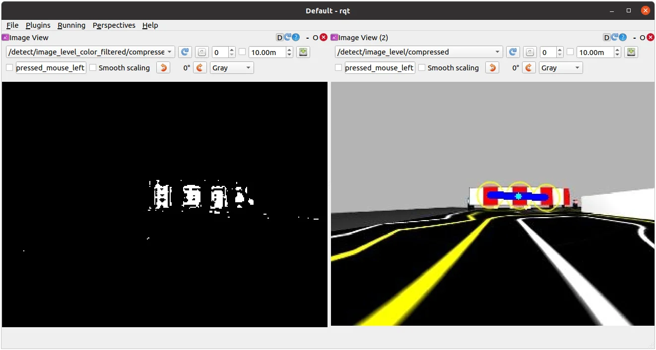
-
Excute rqt_reconfigure.
$ rosrun rqt_reconfigure rqt_reconfigure
-
Adjust parameters in the
detect_level_crossingin the left column to enhance the detection of the crossing gate.
-
Open
level.yamlfile located at turtlebot3_autorace_detect/param/level/.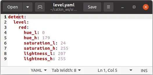
-
Write any modified values to the file and save.
Testing Level Crossing Detection
-
Close all terminals or terminate them with
Ctrl+C -
Open a new terminal and launch Autorace Gazebo simulation. Launch
roscorewith the roslaunch command.
$ roslaunch turtlebot3_gazebo turtlebot3_autorace_2020.launch
- Open a new terminal and launch the intrinsic calibration node.
$ roslaunch turtlebot3_autorace_camera intrinsic_camera_calibration.launch
- Open a new terminal and launch the extrinsic calibration node.
$ roslaunch turtlebot3_autorace_camera extrinsic_camera_calibration.launch
- Open a new terminal and launch the level crossing detection node.
$ roslaunch turtlebot3_autorace_detect detect_level_crossing.launch
- Open a new terminal and execute the rqt_image_view.
$ rqt_image_view
- Check the image topic:
/detect/image_level/compressed.
How to Run Level Crossing Mission
-
Close all terminals or terminate them with
Ctrl+C -
Open a new terminal and launch Autorace Gazebo simulation. Lauch
roscorewith the roslaunch command.
$ roslaunch turtlebot3_gazebo turtlebot3_autorace_2020.launch
- Open a new terminal and launch the intrinsic calibration node.
$ roslaunch turtlebot3_autorace_camera intrinsic_camera_calibration.launch
- Open a new terminal and launch the keyboard teleoperation node.
Drive the TurtleBot3 along the lane and stop before the stop traffic sign.
$ roslaunch turtlebot3_teleop turtlebot3_teleop_key.launch
- Open a new terminal and launch the autorace core node with a specific mission name.
$ roslaunch turtlebot3_autorace_core turtlebot3_autorace_core.launch mission:=level_crossing
- Open a new terminal and launch the Gazebo mission node.
$ roslaunch turtlebot3_autorace_core turtlebot3_autorace_mission.launch
- Open a new terminal and enter the command below. This will prepare to run the level crossing mission by setting the
decided_modeto2.
$ rostopic pub -1 /core/decided_mode std_msgs/UInt8 "data: 2"
Tunnel
Tunnel is the sixth mission of TurtleBot3 AutoRace 2020. The TurtleBot3 must avoid obstacles in the unexplored tunnel and exit successfully.
How to Run Tunnel Mission
NOTE: Change the navigation parameters in the turtlebot3/turtlebot3_navigation/param/ file. If you slam and make a new map, Place the new map in the turtlebot3_autorace package you've placed in /turtlebot3_autorace/turtlebot3_autorace_driving/maps/.
-
Close all terminals or terminate them with
Ctrl+C -
Open a new terminal and launch Autorace Gazebo simulation. Launch
roscorewith the roslaunch command.
$ roslaunch turtlebot3_gazebo turtlebot3_autorace_2020.launch
- Open a new terminal and launch the intrinsic calibration node.
$ roslaunch turtlebot3_autorace_camera intrinsic_camera_calibration.launch
- Open a new terminal and launch the keyboard teleoperation node.
Drive the TurtleBot3 along the lane and stop before the tunnel traffic sign.
$ roslaunch turtlebot3_teleop turtlebot3_teleop_key.launch
- Open a new terminal and launch the autorace core node with a specific mission name.
$ roslaunch turtlebot3_autorace_core turtlebot3_autorace_core.launch mission:=tunnel
- Open a new terminal and enter the command below. This will prepare to run the tunnel mission by setting the
decided_modeto2.
$ rostopic pub -1 /core/decided_mode std_msgs/UInt8 "data: 2"