AI Worker x NVIDIA Isaac ROS cuMotion
Full Demo
1. Overview
Sending a robot arm to a target pose is only part of a manipulation task. The robot must also avoid its own body, fixed structures, newly introduced obstacles, and any object held by the gripper. This becomes especially important for AI Worker, where a lift and two 7-DoF arms operate in the same workspace.
NVIDIA Isaac ROS provides GPU-accelerated ROS 2 packages for perception, mapping, and manipulation. For motion planning, Isaac ROS cuMotion integrates with MoveIt 2 and generates smooth, collision-free trajectories for robot arms. It can also consume an ESDF reconstructed by Isaac ROS Nvblox, allowing depth observations to participate directly in collision checking.
This project applies these capabilities to AI Worker's dual-arm control stack and RViz interface. The demonstration covers four stages:
- End-effector target poses for the left arm, right arm, and whole body
- Static-scene collision-aware planning with predefined obstacle geometry
- Dynamic-scene collision-aware planning with a depth-based ESDF map
- Attached-object collision-aware planning that accounts for a carried object
The result is one planning workflow that can move from a simple pose target to collision-aware manipulation in a changing workspace.
2. System Architecture
The system is divided between AI Worker and a GPU workstation. AI Worker runs
the camera drivers and hardware controllers, while the workstation runs cuMotion, robot segmentation, and Nvblox inside the cyclo_solution
environment.
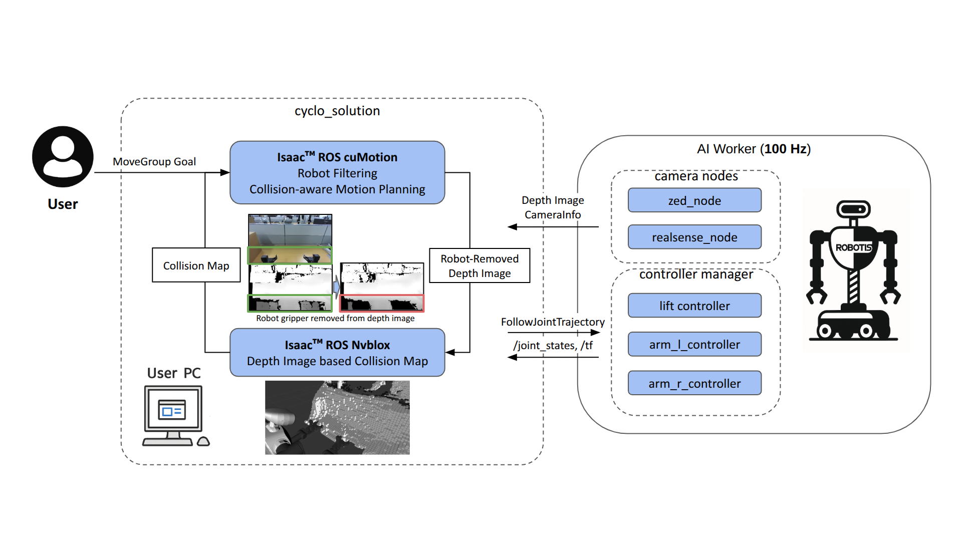
AI Worker streams camera and robot state data to the GPU workstation; cuMotion returns trajectories to the robot controllers.
The data flow is as follows:
- The head-mounted ZED camera and wrist-mounted RealSense D405 cameras publish depth images and camera information.
- The robot segmenter uses the robot model, joint states, and TF transforms to remove AI Worker from each depth image.
- Nvblox fuses the filtered depth streams and builds a TSDF and ESDF of the workspace.
- A target submitted through RViz enters MoveIt 2 as a
MoveGrouprequest. - The
isaac_ros_cumotion_moveitplanning plugin forwards the request and the current collision world to the cuMotion backend. - The planned trajectory is sent to the lift and arm controllers through the
FollowJointTrajectoryinterface.
Robot state continuously returns through /joint_states and /tf, keeping the
planner, depth filtering, visualization, and physical robot synchronized.
| Interface | Role in the system |
|---|---|
Depth image + CameraInfo | Workspace observation from the ZED and D405 cameras |
| Robot-removed depth | Input to Nvblox without the robot's own geometry |
| ESDF | Distance-to-obstacle representation used by cuMotion |
MoveIt MoveGroup request | Target pose, planning group, and planning constraints |
FollowJointTrajectory | Planned joint trajectory sent to AI Worker |
/joint_states and /tf | Current robot configuration and frame transforms |
3. From the Robot Model to a cuMotion Plan
cuMotion uses the robot's URDF for kinematics and an XRDF model for collision checking. In the XRDF, each robot link is approximated by a set of collision spheres. These spheres provide a lightweight representation for repeatedly checking self-collision and world-collision distances during optimization.
For AI Worker, the collision spheres were created and refined in Isaac Sim using the Lula Robot Description and XRDF Editor. The editor can generate spheres from each link mesh, supports manual adjustment of their positions and radii, and exports the result as a cuMotion XRDF file. The exported spheres are then visualized in RViz during motion planning process.
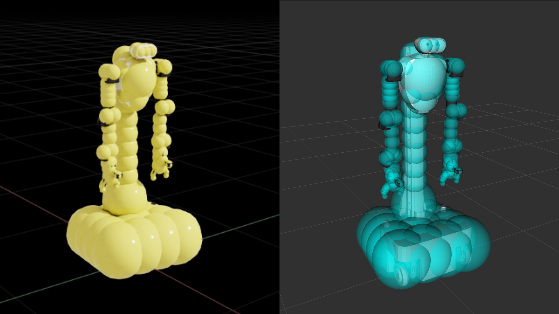
XRDF collision spheres in Isaac Sim (left) and the corresponding visualization during motion planning (right).
Collision-sphere tuning: Collision spheres should cover the robot without becoming unnecessarily large. Sparse coverage can miss parts of a link, while oversized spheres make the planner overly conservative.
Separate XRDF configurations are provided for the four MoveIt planning groups defined in the SRDF:
| Planning group | Controlled joints |
|---|---|
arm_l | Left arm |
arm_r | Right arm |
both_arms | Left and right arms |
wholebody | Lift and both arms |
When the planning group changes in RViz, the group router loads the matching XRDF and collision spheres into the cuMotion backend. This supports left-arm, right-arm, dual-arm, and whole-body planning through a single planning stack.
The Isaac ROS cuMotion MoveIt plugin allows the operator to set a target in RViz and use cuMotion as the MoveIt planning pipeline without changing the standard planning workflow.
Basic launch
Start and enter the development container, then launch the common planning stack:
cd cyclo_solution/docker
./container.sh start
./container.sh enter

ros2 launch cyclo_cumotion_bringup cumotion_moveit.launch.py
With this launch, depth-based world collision checking and object attachment remain disabled. They can be enabled independently for the demonstrations described below.
4. Collision-Aware Planning
4.1 End-effector target poses
The first demonstration establishes the basic planning path from RViz to the
physical robot. An operator selects arm_l, arm_r, or wholebody, defines an
end-effector target pose, and requests a plan. cuMotion evaluates the robot's
kinematics and collision model, then returns a valid joint trajectory for the
selected group.
This is also a useful model-validation step. Incorrect joint limits, frame definitions, or collision spheres often appear immediately as an unreachable goal or an unexpected detour.
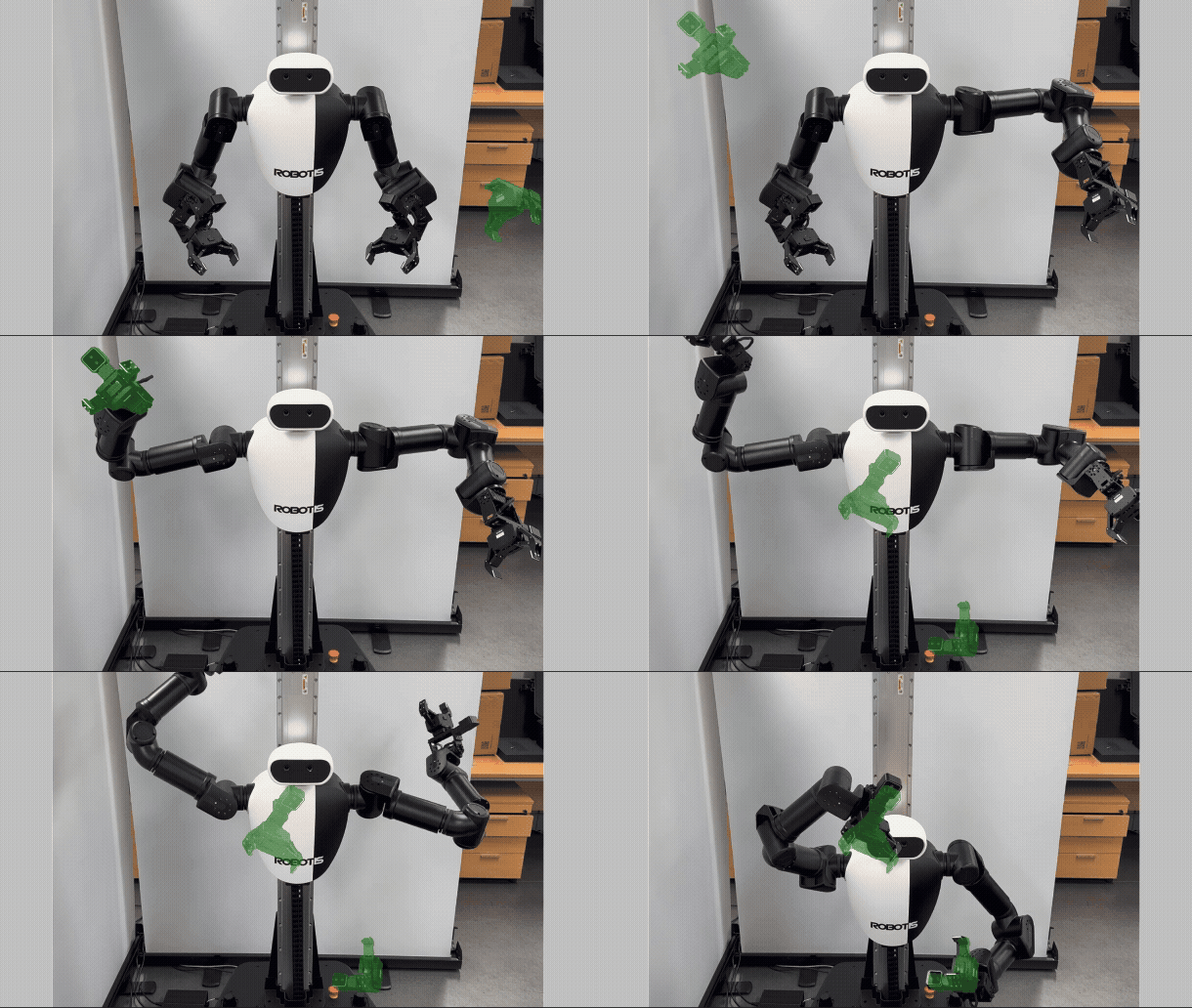
Target-pose planning for the left arm, right arm, and whole-body planning group.
4.2 Static-scene collision avoidance
Many workcells contain structures that remain fixed during operation, such as tables, shelves, fixtures, and safety barriers. These structures can be added to the MoveIt planning scene as collision geometry. cuMotion then plans against both the static scene and the robot's self-collision model.
For this demonstration, the static scene models a shelf and its supporting desk. Each shelf panel is represented by a box collision object, including the top, bottom, side, back, and intermediate panels. The end effector repeatedly moves between different shelf compartments. cuMotion must guide it into and out of each narrow opening without colliding with the surrounding panels.
Creating the static scene
A static scene can be created directly in RViz:
- Open MotionPlanning → Scene Objects.
- Add and position collision objects.
- Check the dimensions and poses in the planning frame.
- Select Export Scene Geometry and save the result as a
.scenefile.
The exported file is a text representation of the scene. Each object records its name, pose, primitive type, dimensions, and display color. Our example scene is stored at:
cyclo_cumotion/cyclo_cumotion_moveit_config/config/scene/two_open_boxes.scene
Scene validation: When exact dimensions and poses are known, the .scene file can also be edited
manually. Import the result into RViz and compare it with the physical workspace
before planning.
Loading the static scene
The default shelf scene is loaded by enabling the static-scene option:
ros2 launch cyclo_cumotion_bringup cumotion_moveit.launch.py \
  enable_static_scene:=true
To load another .scene file, pass its absolute path inside the container:
ros2 launch cyclo_cumotion_bringup cumotion_moveit.launch.py \
  enable_static_scene:=true \
  moveit_collision_objects_scene_file:=/absolute/path/to/custom_scene.scene
During startup, the scene is added to the MoveIt planning scene shown in RViz and supplied to cuMotion as static collision geometry. The planner can then generate trajectories between the shelf compartments while maintaining clearance from every modeled panel.
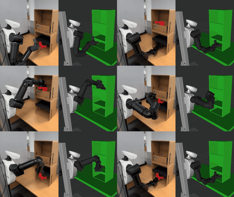
The end effector moves between shelf compartments represented by static collision geometry.
4.3 Dynamic-scene collision avoidance with Nvblox
A predefined scene cannot represent a box or person that enters the workspace after startup. For these changes, the system builds a live collision map from depth data.
The head ZED and two wrist D405 cameras observe the workspace from complementary viewpoints. Before fusion, the Isaac ROS cuMotion robot segmenter masks pixels occupied by the robot. Without this step, Nvblox could reconstruct the moving arms as environmental obstacles and cause the planner to avoid the robot's own depth image.
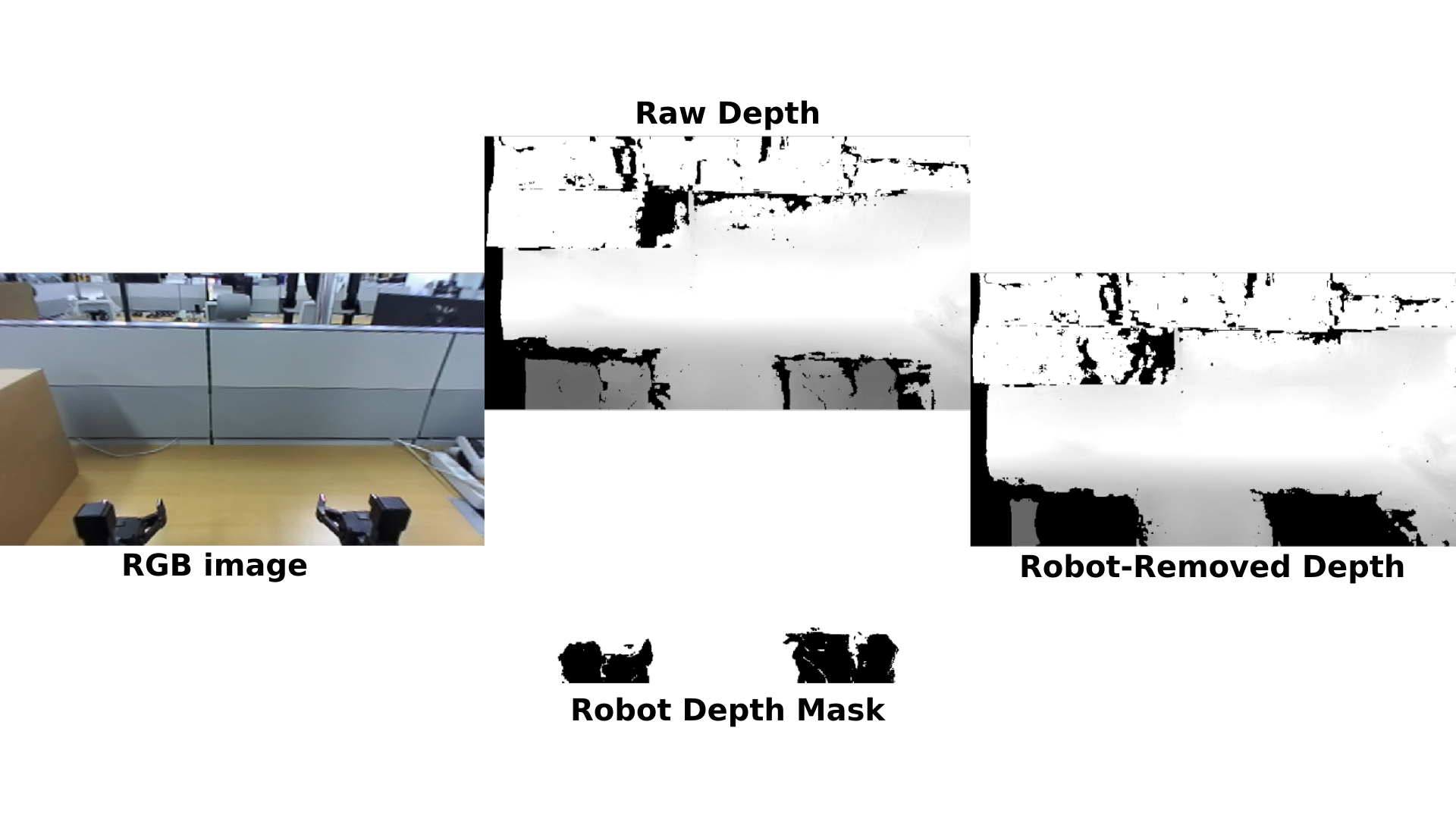
Nvblox integrates the robot-removed depth into two related representations:
- A TSDF reconstructs observed surfaces in 3D.
- An ESDF stores the signed distance to the nearest obstacle.
The ESDF is especially useful for optimization-based planning because cuMotion can query obstacle distance throughout a candidate trajectory. Enable this pipeline with:
ros2 launch cyclo_cumotion_bringup cumotion_moveit.launch.py \
  read_esdf_world:=true \
  nvblox_camera_set:=all
nvblox_camera_set can also select only the head camera (head) or the two
wrist cameras (wrists). The launch sequence waits for a usable ESDF before
starting the planner, preventing an early request from being evaluated against
an empty map.
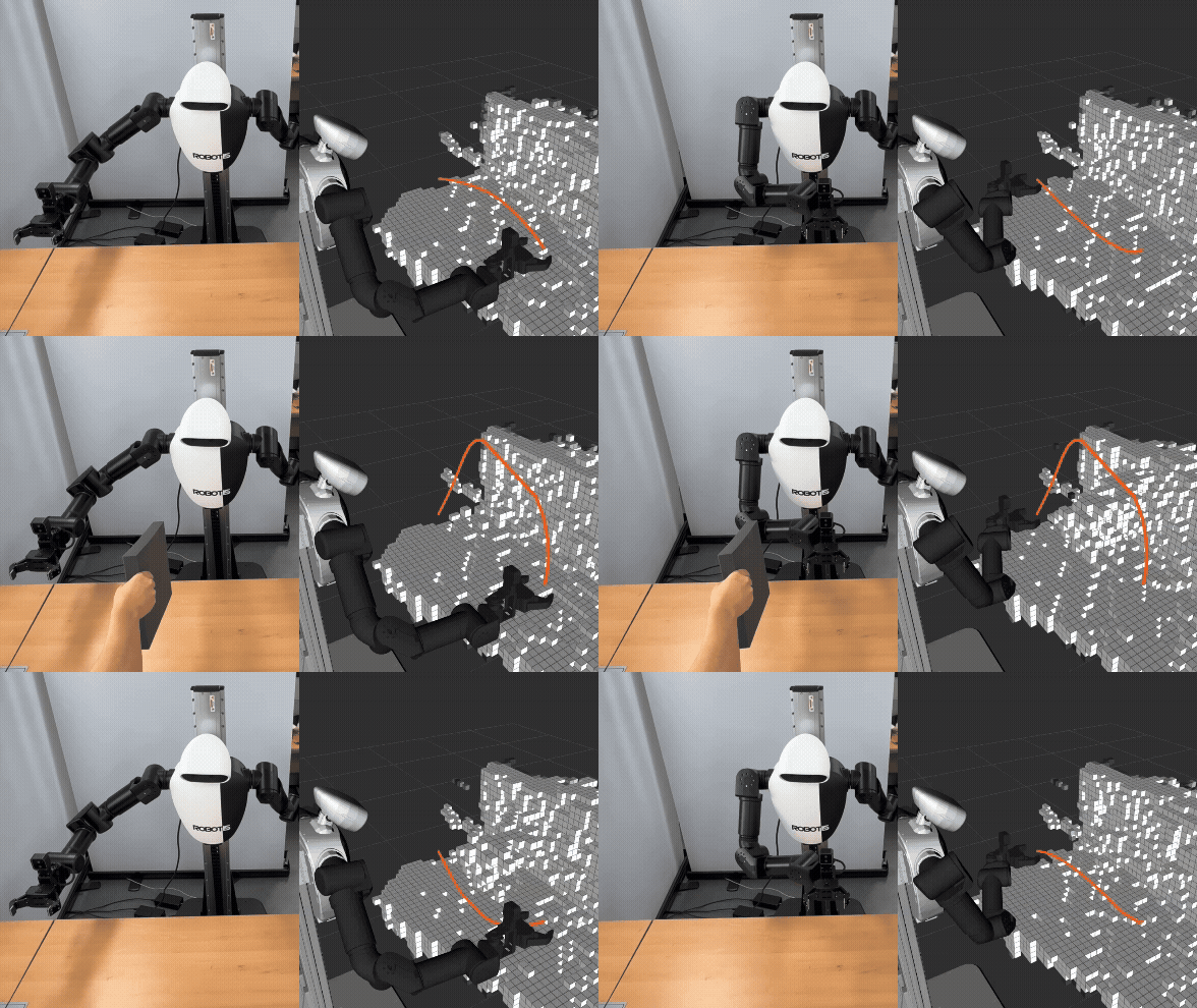
In the demonstration, the arm repeatedly plans between two poses. When an obstacle is introduced, it appears in the ESDF and the next planning request produces a collision-free route around it. After the obstacle is removed and the map updates, the planner can return to a more direct, smooth trajectory. This is replanning against an updated world model; it is not a claim that the executing trajectory is continuously modified in mid-motion.
5. Attached-Object Collision Avoidance
Robot-only collision checking is not sufficient after a grasp. A gripper may clear an obstacle while the carried object still intersects it. Object attachment solves this by making the grasped object part of the robot's collision model for subsequent plans.
The Isaac ROS cuMotion object attachment package approximates the attached geometry with collision spheres and adds them to the active cuMotion robot description. NVIDIA's interface supports sphere, cuboid, and mesh geometry. Our integration adds a predefined-object catalog so that a known object can be attached to either end effector with a service call.
The attachment workflow is:
- Define the object's geometry and pose relative to the grasp frame.
- Attach it to the selected end effector.
- Update every planning group with the attached collision geometry.
- Clear the object's occupied ESDF region when depth-based mapping is active, so the same object is not represented both as carried geometry and as a separate world obstacle.
- Plan and execute while checking collisions against both the robot and the carried object.
- Detach the object and restore the original collision model after placement.
Start the stack with object attachment enabled:
ros2 launch cyclo_cumotion_bringup cumotion_moveit.launch.py \
  read_esdf_world:=true \
  enable_object_attachment:=true
The current demo catalog defines table_box, including its dimensions, pose,
and default right-end-effector frame. It can be attached and detached as
follows:
ros2 service call \
  /cyclo_cumotion/object_attachment/attach_by_name \
  robotis_interfaces/srv/AttachObjectByName \
  "{object_name: table_box, attachment_frame: end_effector_r_link}"

ros2 service call \
  /cyclo_cumotion/object_attachment/detach \
  std_srvs/srv/Trigger '{}'
The following comparison makes the difference visible. Without attachment, the planned robot links avoid the obstacle, but the carried object can collide. With attachment, the planner accounts for the object's full motion and selects a trajectory that keeps both the robot and carried object clear.
In this demonstration, the object geometry and attachment pose are supplied by the predefined-object catalog.
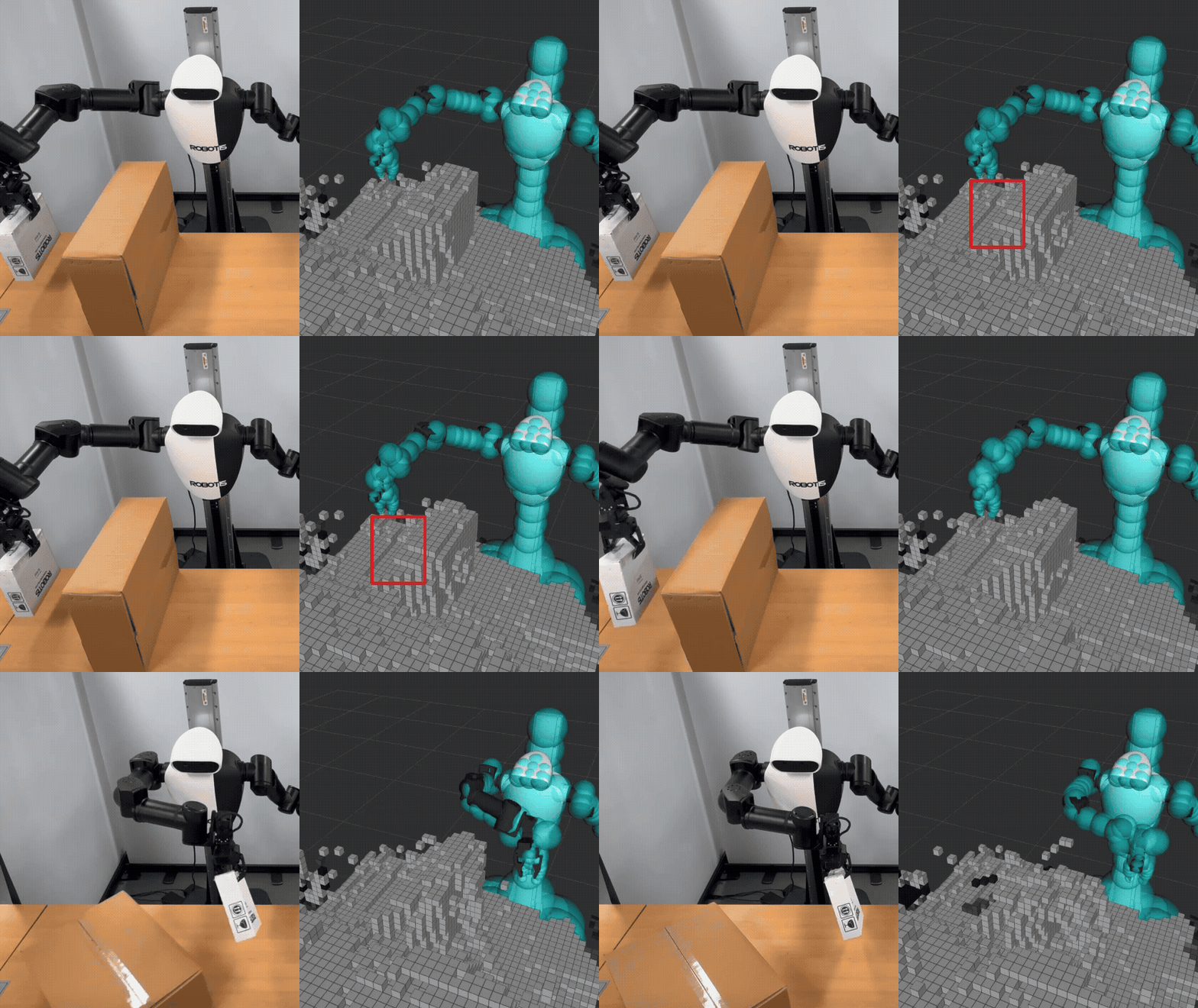
Without attachment, carried-object collisions are not considered, and the box hits the obstacle.
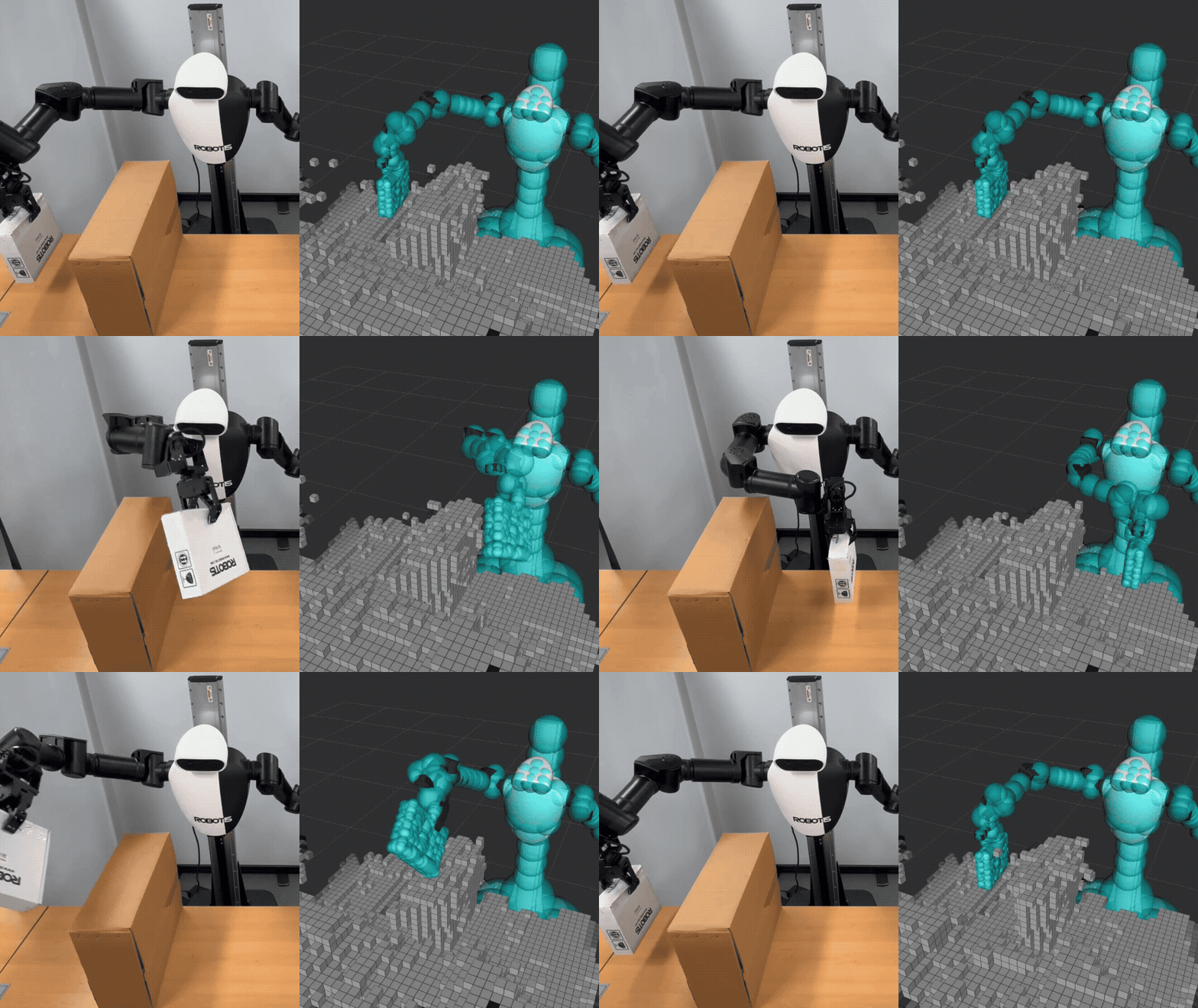
With attachment, carried-object collisions are considered, and the box avoids the obstacle.
6. Limitations
Wired depth streaming
Depth-based collision mapping depends on the timely delivery of multiple depth streams, camera information, joint states, and TF. Packet loss or latency can delay ESDF updates and leave the collision map incomplete.
Stable camera streaming: Connect AI Worker's rear USB 3.0 port to the user PC through a USB-to-Ethernet adapter and an Ethernet cable. This direct connection provides a stable camera feed.
Planning and perception boundaries
Nvblox can reconstruct only the surfaces observed by the cameras, so occlusion, limited viewpoints, and noisy depth can produce incomplete geometry. In addition, the dynamic-scene demonstration replans against the latest ESDF; it does not continuously modify an executing trajectory or replace safety-rated sensing and control.
7. What's Next
AI Worker currently runs JetPack 6.2, so the Isaac ROS pipeline used in this project runs on an external GPU workstation rather than on the robot's Orin. To run the pipeline on the robot, users can upgrade AI Worker to a JetPack release compatible with the required Isaac ROS environment.
Another possible extension is a perception-driven attachment pipeline that converts a detected object's 3D bounding box and pose into collision geometry, then automatically attaches that geometry to the selected end effector. This would connect Isaac ROS perception outputs directly to collision-aware manipulation.