AI Worker x Isaac ROS CenterPose Pick & Place
Full Demo
A demo video of the CenterPose pick-and-place operation.
1. Overview
We built pick-and-place on the AI Worker using NVIDIA's Isaac ROS CenterPose to get a 6DoF pose (position + orientation) for whatever object the ZED camera sees.
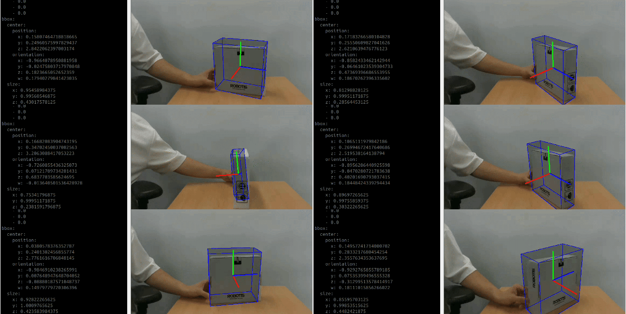
From there, that position and orientation go through a coordinate transformation and a quaternion transformation, and the result drives the arm as a MoveL target through cyclo_motion_controller_ros. This page writes up our approach to that process, including:
- Coordinate transformation (recovering a real position from a detection)
- Quaternion transformation (converting detected orientation into a gripper angle)
- Driving the arm with MoveL
- Visualization (point cloud + bbox markers in RViz)
The full code is on the feature-centerpose branch.
2. System Architecture
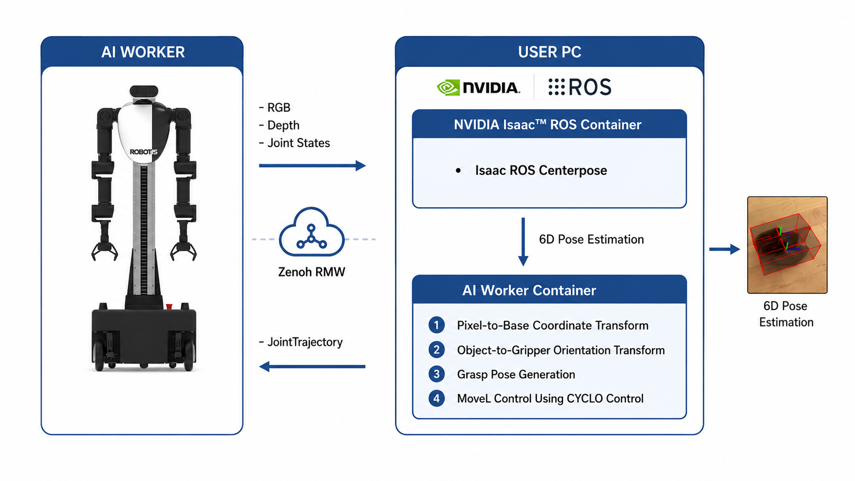
ZED camera → Isaac ROS CenterPose (GPU PC) → Vision Pick & Place node → AI Worker (cyclo_control / hardware interface).
CenterPose needs a GPU, so it runs inside a separate Isaac ROS container on a user PC — the AI Worker itself only runs its own onboard bringup. That splits the system across three containers, bridged over the network with Zenoh RMW:
- AI Worker: Runs the robot bringup (
ffw_bringup) and the Zenoh router. The only thing physically wired to the arms and cameras. - User PC — Isaac ROS container: Runs
isaac_ros_centerposewith a Triton-served model, one ofcenterpose_bottle/centerpose_box/centerpose_shoe, publishingvision_msgs/Detection3DArrayon/centerpose/detections. - User PC — worker container: Runs the pick-and-place nodes plus
cyclo_motion_controller_ros(the MoveL controller that turns Cartesian targets into actual joint motion) and the RViz visualization.
For a stable camera feed, the AI Worker's rear USB 3.0 port is connected to the user PC with a wired cable.
3. Object-Specific Variants
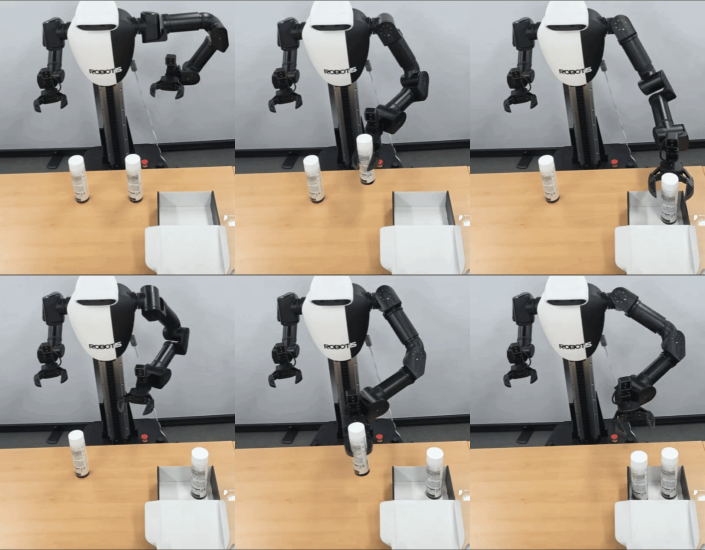
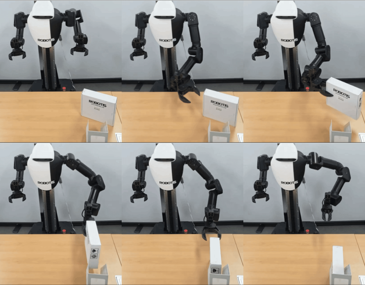
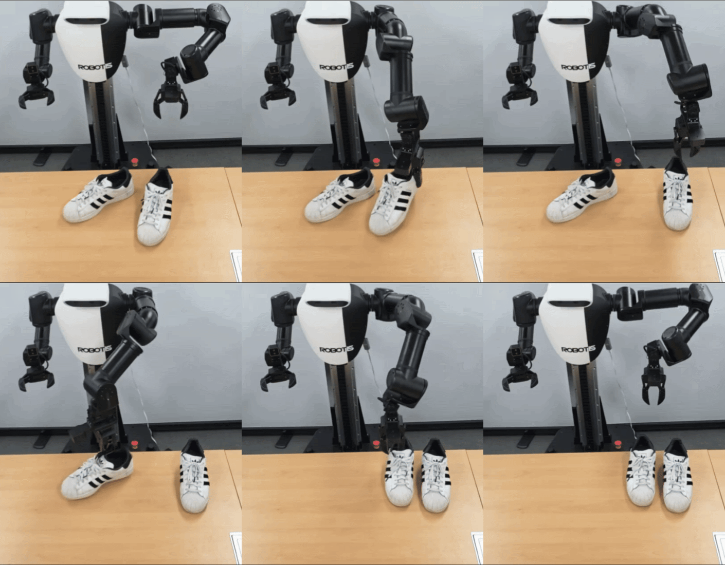
centerpose_bottle, centerpose_box, and centerpose_shoe share the same coordinate transformation mechanism but differ in how they grasp and where the object's orientation actually matters:
centerpose_bottle | centerpose_box | centerpose_shoe | |
|---|---|---|---|
| Grasp approach | Side grasp, fixed orientation | Side grasp, roll follows box yaw | Top-down grasp, yaw follows shoe |
| Orientation source | ✕ | Detected quaternion → signed angle → roll | Detected quaternion → signed angle → yaw |
| Motion | Pick and place | Pick and insert | Pick and align |
4. Coordinate Transformation: From Pixel to Base Frame
CenterPose tells us which pixel contains the object, the ZED depth image tells us how far away that pixel is, and TF converts the resulting 3D point into base_link.
Given the camera's intrinsics (CameraInfo) and a detection's position, this is how that gets turned into a real position in the robot's base_link frame — at its core, just a standard rigid-body transform:
is a 3D point, and , come straight from a TF lookup: rotates the camera's axes to line up with base_link's, and is the position of the camera-frame origin, expressed in the base_link frame.
Getting a trustworthy in the first place is most of the work below. CenterPose estimates pose up to scale, so its translation isn't metric-accurate enough for our grasping setup — we only use the image ray implied by its detected center (i.e. its 2D pixel direction), and recover metric depth separately from the ZED's registered depth image:
Step 1 — forward-project CenterPose's reported 3D point to a pixel with the standard pinhole camera model:
( = focal length, = principal point — both from CameraInfo; = CenterPose's 3D point in the camera frame; = the resulting pixel.)
def _project_to_pixel(self, camera_info, position, log):
    fx = camera_info.k[0]
    fy = camera_info.k[4]
    cx = camera_info.k[2]
    cy = camera_info.k[5]
    u = fx * (position.x / position.z) + cx
    v = fy * (position.y / position.z) + cy
    return u, v
Step 2 — sample real depth at that pixel. _sample_depth takes the median depth over a small window around the pixel and rejects invalid/zero readings.
The ZED camera's depth mode is set to ULTRA for the most accurate depth reading, via depth.depth_mode in ffw_bringup/config/common/common_stereo.yaml.
Step 3 — back-project the pixel + real depth into a 3D camera-frame point, using the inverse of the same pinhole model:
( = the pixel from Step 1; = the real depth sampled at that pixel; = the resulting 3D point, back in the camera frame.)
def _real_camera_point(self, camera_info, u, v, depth_image, depth_msg, log):
    fx, fy, cx, cy = camera_info.k[0], camera_info.k[4], camera_info.k[2], camera_info.k[5]
    depth = self._sample_depth(depth_image, depth_msg, int(round(u)), int(round(v)))
    if depth is None:
        return None
    return np.array(
        [(u - cx) * depth / fx, (v - cy) * depth / fy, depth], dtype=np.float64
    )
Step 4 — transform to base_link with a rigid-body TF transform (rotate, then translate). For a unit quaternion , the rotation itself is the standard closed-form quaternion-vector rotation, which avoids ever building a 3x3 rotation matrix:
( = the point to rotate, = the camera→base_link rotation as a quaternion, = the rotated point.)
def _rotate_vector(vector, q):
    q_vector = q[:3]
    uv = np.cross(q_vector, vector)
    uuv = np.cross(q_vector, uv)
    return vector + 2.0 * (q[3] * uv + uuv)

# camera_transform = (transform_q, t), from tf_buffer.lookup_transform(...)
transform_q, t = camera_transform
point = self._rotate_vector(np.asarray(real_point_cam, dtype=np.float64), transform_q) + t
Step 5 — assemble the position. x/y get the transformed point plus a small calibrated offset; z is deliberately not taken from the pipeline above at all:
pose.pose.position.x = float(point[0] + self.grasp_position_offset[0])
pose.pose.position.y = float(point[1] + self.grasp_position_offset[1])
pose.pose.position.z = fixed_z + self.grasp_position_offset[2]
fixed_z is a measured constant (fixed_grasp_z), not the depth-derived Z — even real depth readings aren't reliable enough at the exact grasp height. Box and shoe go a step further and add a small correction proportional to how far off-center the pixel is, since the depth reading itself drifts slightly with position in frame.
5. From Object Quaternion to Gripper Quaternion
Compare the detected orientation with a calibrated reference, keep only the rotation needed for grasping, and convert it into the gripper's target quaternion.
For the box and shoe, orientation also has to be converted — from CenterPose's detected quaternion into a gripper target quaternion. The technique is to decompose the relative rotation between the detected quaternion and a fixed reference orientation into an axis + angle, then rebuild a gripper quaternion from only the part of that rotation that actually matters for the grasp:
Step 1 — get a signed angle between the robot's front-facing direction and the object's angle. box_yaw_reference_orientation is a measured constant. It's the orientation CenterPose reports when the object happens to be aligned with the robot's front ("0°").
To find how far off from that the object currently is, multiply the conjugate of the reference quaternion by the currently detected orientation (object_q). This gives the relative rotation between the two, which is then decomposed into an axis + angle. The axis-angle conversion returns a non-negative angle (); the rotation direction instead ends up encoded in which way the axis points. So a signed yaw is recovered by comparing that axis against a configured reference axis:
( is the conjugate/inverse of the reference quaternion, and is quaternion multiplication.)
def _signed_box_yaw(self, object_q):
    relative_q = self._quaternion_multiply(
        self._quaternion_conjugate(self.box_yaw_reference_orientation), object_q
    )
    axis, angle = self._quaternion_axis_angle(relative_q)
    sign = 1.0 if np.dot(axis, self.box_yaw_axis) >= 0.0 else -1.0
    return sign * angle, angle
Step 2 — 180° front/back flip correction. CenterPose occasionally reports an object rotated 180° from its true orientation. In our calibrated operating range, this front/back ambiguity usually shows up as an unsigned relative angle larger than a configured threshold — an empirical heuristic, not a general guarantee, since a genuinely large rotation would look the same. We treat detections past that threshold as a flip and apply a local-Y correction:
object_yaw, raw_angle = self._signed_box_yaw(object_q)
if math.degrees(raw_angle) > self.box_yaw_flip_threshold_deg:
    object_q = self._quaternion_multiply(object_q, self._LOCAL_Y_180_FLIP)
    object_yaw, _ = self._signed_box_yaw(object_q)
Step 3 — turn that single angle into a gripper quaternion. The measured angle is passed through a small linear calibration (fit from real measurements, not derived analytically) to get the actual gripper angle, clamped to the range it was measured in, then composed with a fixed tool-mounting offset:
( = the box's signed yaw from Step 1; = the measured scale/offset calibration; = fixed constants; = the fixed gripper-mounting offset.)
# linear fit measured on the real robot: gripper roll for a given object yaw
raw_roll_deg = math.degrees(
    self.grasp_roll_from_yaw_scale * object_yaw + self.grasp_roll_offset
)
# the fit above is only valid within the range it was measured in
clamped_roll_deg = min(max(raw_roll_deg, self.roll_clamp_min_deg), self.roll_clamp_max_deg)
roll = self._wrap_angle(math.radians(clamped_roll_deg))
# only roll comes from the detection; pitch/yaw are fixed constants
base_q = self._quaternion_from_euler(roll, self.grasp_fixed_pitch, self.grasp_fixed_yaw)
# correct for how the gripper is physically mounted on the arm
target_q = self._quaternion_multiply(base_q, self.tool_orientation_offset)
Pitch and yaw stay fixed here — the grasp always approaches from the same general direction — only roll (box) or yaw (shoe) is ever driven by the detection. Bottle skips this whole section: it always uses one fixed, pre-measured orientation regardless of what CenterPose reports.
That target_q is what actually ends up on the pose that Section 6 hands off to MoveL:
pose.pose.orientation = self._quaternion_message(orientation) # target_q from above
Quick symbol reference (Sections 4–5)
| Symbol | Meaning | Source |
|---|---|---|
| Pixel coordinates in the image | Computed from using /camera_info intrinsics | |
| CenterPose's raw 3D point (camera frame) | /centerpose/detections (Detection3DArray) | |
| Real 3D point, recovered via real depth | Recomputed using /zedm/zed_node/depth/depth_registered | |
Camera→base_link rotation / translation | TF (tf_buffer.lookup_transform) | |
| The object's orientation as CenterPose detected it | /centerpose/detections (Detection3DArray) | |
| A measured "0°" reference orientation | Fixed parameter, measured once — not a topic | |
| The final gripper target orientation | Computed; published as part of the MoveL message |
6. Driving the Arm with MoveL
Once Sections 4–5 produce a target position and gripper quaternion on the same pose object, none of this involves any inverse kinematics on our side — that pose is just packed into a MoveL message and published. An external controller (cyclo_motion_controller_ros) is the one that actually solves IK and drives the joints from there:
def _move_l(self, pose, duration=None):
    if not self._wait_for_subscriber(self.movel_pub, self.movel_topic):
        return False
    duration = self.movel_duration if duration is None else duration
    msg = MoveL()
    msg.pose = pose          # the PoseStamped built in Sections 4–5
    msg.time_from_start = self._duration(duration)
    self.movel_pub.publish(msg)
    return self._cancelable_sleep(duration + self.settle_time)
A single computed pose isn't the whole pick, though — it's just the "insert" point. The other waypoints (pregrasp, lift) are derived from that same pose with simple offsets along the gripper's own approach axis, not separate detections:
approach_dir = self._rotate_vector(np.array([0.0, 0.0, -1.0]), grasp_q)

# grasp_pose backed off along approach_dir, before actually grabbing
pregrasp_pose = self._copy_pose(grasp_pose)
pregrasp_pose.pose.position.x -= approach_dir[0] * self.pregrasp_distance
pregrasp_pose.pose.position.y -= approach_dir[1] * self.pregrasp_distance
pregrasp_pose.pose.position.z -= approach_dir[2] * self.pregrasp_distance
Each of those poses (pregrasp, insert, lift, place, ...) just gets passed to _move_l in order, one after another, to actually run the pick.
7. Visualization
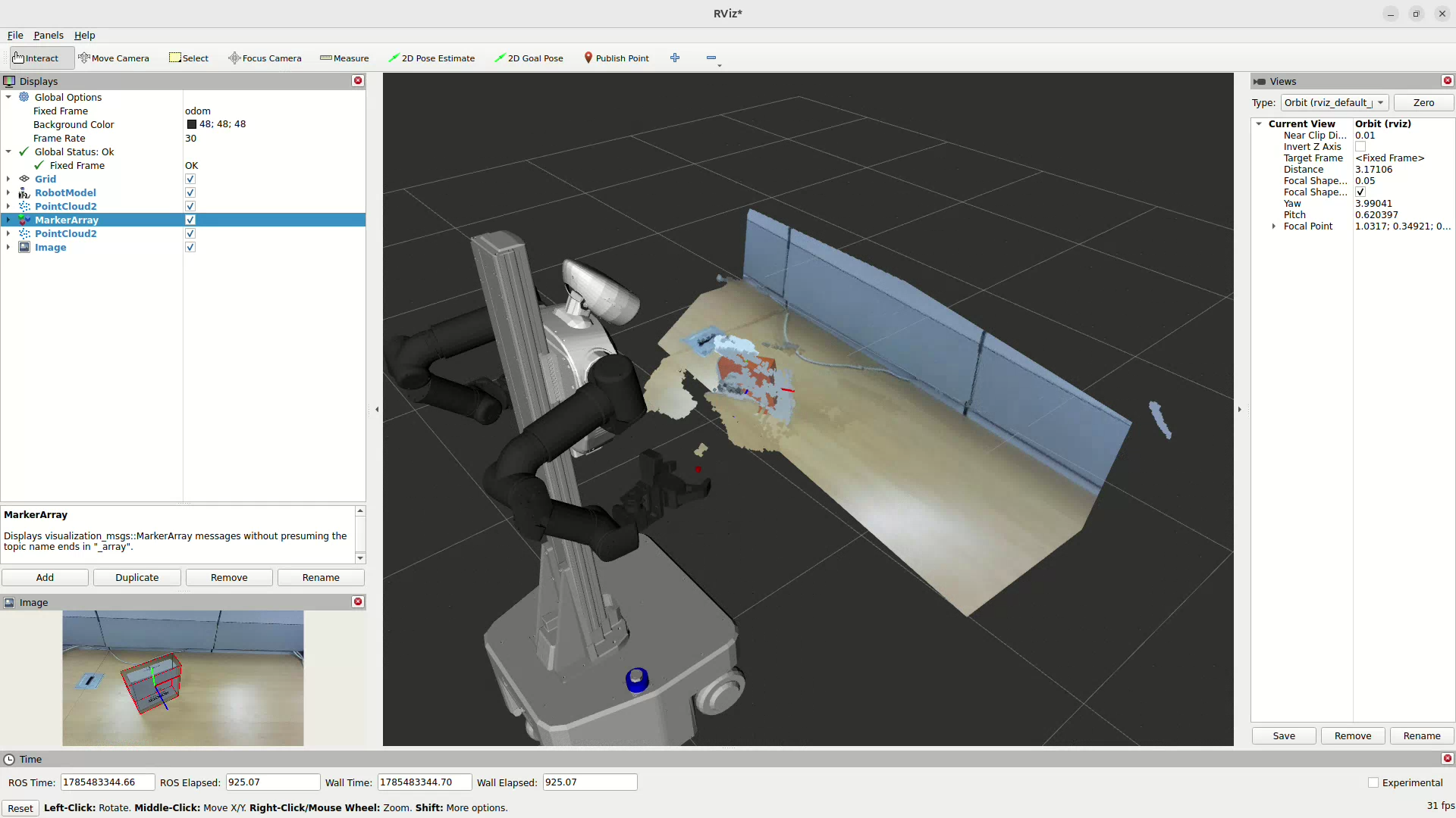
centerpose_pointcloud renders a cropped, table-flattened RViz view with corrected bounding-box markers — for debugging the pipeline above, not for control:
-
Crop: Keep only points inside an axis-aligned box in front of the robot, then drop anything below the table once it's found — mainly just to keep the RViz view clean instead of showing the whole raw scene.
-
Table plane + wall: to show the table as a clean, real-size flat surface instead of noisy raw depth points, its plane is found with a small RANSAC over the cropped cloud (sample 3 points, fit a plane, keep whichever triple has the most inliers), refined with an SVD over those inliers, and smoothed frame-to-frame with an EMA. Once the plane is found, both the table and a wall rising from its far edge (so the cloud doesn't just cut off abruptly) are built the same way — a grid of 3D points across the flat surface, each re-projected into the color camera to pull its real pixel color:
# Try a plane through 3 random points, count how many other points agree with it
normal = np.cross(p1 - p0, p2 - p0)
normal /= np.linalg.norm(normal)
distances = np.abs((sample_points - p0) @ normal)
inlier_count = (distances < self.table_plane_distance_threshold).sum()
# ...repeat for many random triples, keep whichever got the most inliers

# Real color for a 3D point on that plane
u_px = fx * point_cam[0] / point_cam[2] + cx
v_px = fy * point_cam[1] / point_cam[2] + cy
color = bgr[v_px, u_px]
The result is a clean, camera-textured point cloud instead of raw depth.
- Bbox markers: rather than trusting CenterPose's own position and size, this reuses the exact same project → sample-real-depth → back-project trick from Section 4 — just to draw a debug marker instead of a grasp pose:
def _correct_bbox(self, detection, camera_info, depth_image, depth_msg):
    center = detection.bbox.center.position
    u = fx * (center.x / center.z) + cx
    v = fy * (center.y / center.z) + cy

    real_depth = self._sample_depth(depth_image, depth_msg, int(round(u)), int(round(v)))
    size = np.array([detection.bbox.size.x, detection.bbox.size.y, detection.bbox.size.z]) * self.bbox_size_scale

    # real_depth is the object's near surface; its center sits half a box-depth further in
    center_depth = real_depth + 0.5 * float(size.mean())
    position = np.array([(u - cx) * center_depth / fx, (v - cy) * center_depth / fy, center_depth])
    return position, size
In our calibration setup, CenterPose's reported dimensions came out roughly five times larger than the objects' real measured size — not a documented property of the model itself, just what we measured on our own objects and camera — so size gets a fixed bbox_size_scale correction before it's used for anything. center_depth applies a small further correction on top, since the depth camera measures the surface it sees, not the object's actual center.
8. Known Limitations
- Depth camera reads slightly tilted: some offset tuning is usually needed to match your own setup. In our case, the depth camera's readings came out skewed toward one side of the frame, so a position-dependent slope correction may be needed as well.
- Requires a wired connection: getting a stable camera and depth frame stream needs a wired connection between the AI Worker and the user PC — communication isn't reliable enough over Wi-Fi. On-device deployment on an NVIDIA AGX Orin mounted on the robot is needed to remove this dependency.