Using the Remote Controller
This guide explains how to operate AI Sapiens using the RadioMaster remote controller. Use it as a quick reference when you receive the controller and need to check the robot status, select a robot mode, or use Emergency Stop.
For controller hardware specifications and product details, see the RadioMaster Pocket Radio Controller product page.
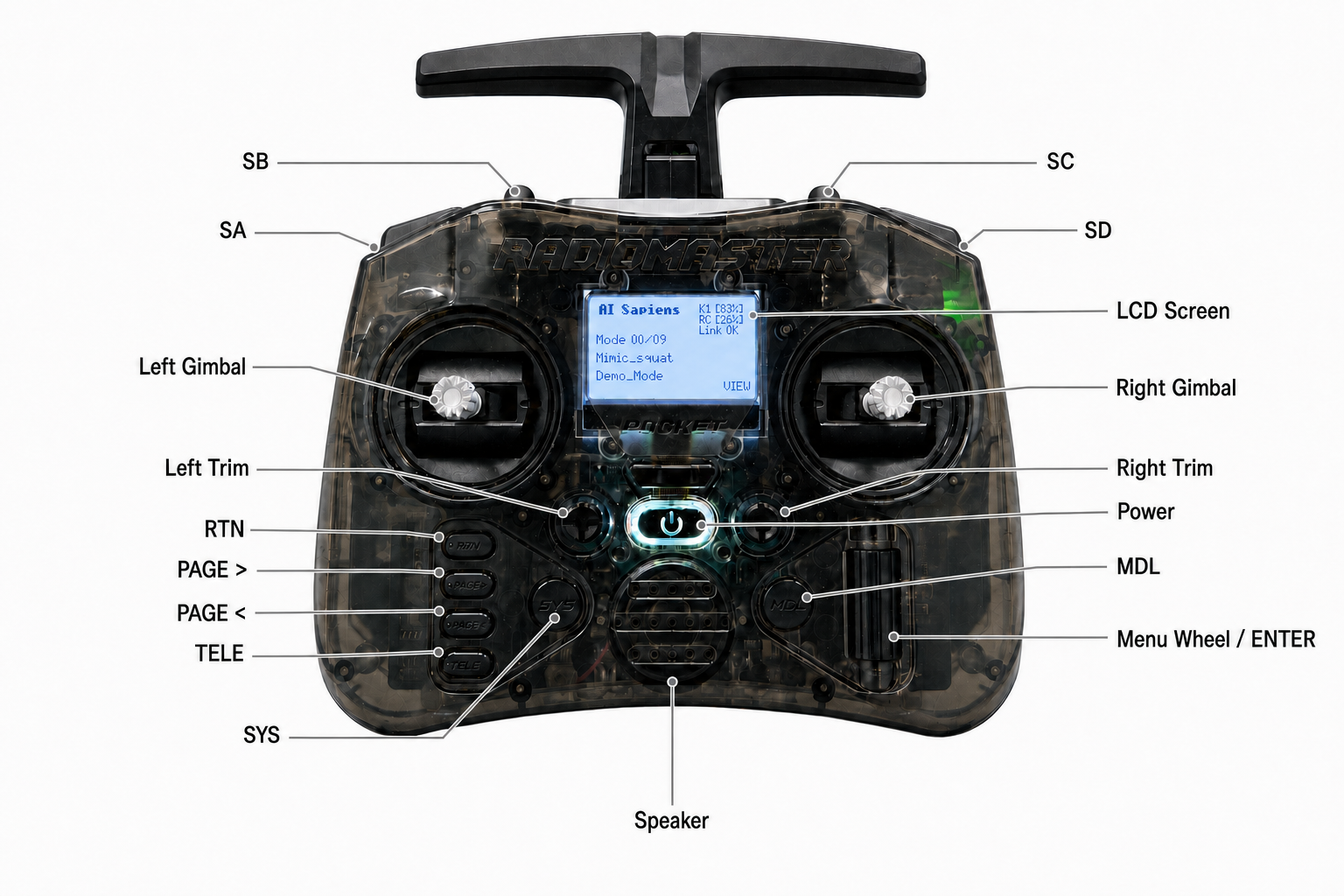
The controller appearance and the information shown on its display may change with future updates.
Before operating the robot, make sure there is enough open space around AI Sapiens and keep your hand near the Emergency Stop controls. Do not continue operating if the controller shows a weak/lost link or missing battery telemetry.
Quick Operation Flow
- Place
SCup for Damping. Press and hold the power button; when the controller vibrates, release the button and confirm that theROBOTISlogo appears. - Turn on AI Sapiens and wait for the controller status to update.
- Confirm that
UPLINK,DOWNLINK, andBATT TELEare healthy on theTELEscreen. - After checking that the area is safe, move
SCto the middle and wait for Ready Pose. - For Velocity control, move
SCdown andSBup. - For a Mimic motion, select it on the main screen, then move
SCandSBdown. - Keep watching the controller display while operating the robot.
Controller Display Pages
| Page | Purpose |
|---|---|
| Main screen | AI Sapiens, battery/link status, and Mimic selection. |
ROBOTIS Docs / Channel Monitor | Documentation QR code and channel output values. |
TELE pages | Robot Status, K1 Battery, ELRS Link, and ELRS RF status and diagnostics. |
Press RTN to return to the main screen. PAGE < and PAGE > cycle through the main display pages.
Press TELE to open Robot Status, then use PAGE > for the other Lua pages.
Select Mimic modes from the main screen, not from the TELE pages.
Status Screen
Press the TELE button to open the controller Lua telemetry screen.
The first page is the main robot status page.
Use PAGE > to move through additional diagnostic pages, and press RTN to return to the main screen.
Main Status Page
The main status page shows the values that matter most during normal operation.
| Display | What it means | Normal reading | What to do if it is not normal |
|---|---|---|---|
UPLINK | Radio control path from the controller to the robot receiver. | OK | If it shows WEAK or LOST, stop operation and move closer to the robot or check the radio link. |
DOWNLINK | Telemetry path from the robot back to the controller. | OK or OK ? | If it shows WEAK, LOST, or LOST ?, robot status values may not update reliably. |
K1 BATT | Robot battery percentage and voltage. | A percentage and voltage value, such as 83% and 24.8V. | If it shows ? or ?V, check BATT TELE. |
BATT TELE | Battery telemetry status. | OK | If it shows NO BATT, the controller is not receiving recent robot battery telemetry. Do not rely on the displayed battery value. |
The controller also shows a compact Link status on the main screen.
Use the meaning below when reading that display:
Main screen Link status meanings
| Link display | Meaning |
|---|---|
OK | The radio link and battery telemetry are healthy. |
WEAK | The radio link is present but weak. Operate only after improving the link. |
LOST | The radio link is lost. Stop operating immediately. |
NO BATT | The radio link is present, but recent robot battery telemetry is missing. Check robot power and battery telemetry before operating. |
The main screen and the TELE pages use slightly different battery telemetry timing.
The main screen follows the native EdgeTX sensor freshness state, while the TELE pages retain the last fresh Bat% or RxBt value for up to 800 ms.
During a brief telemetry delay, the main screen may therefore show Link NO BATT before BATT TELE changes to NO BATT on the Robot Status page.
If NO BATT persists, stop relying on the displayed K1 battery value and check the robot power and telemetry connection.
Diagnostic Pages
Use PAGE > from the TELE screen to view more details.
Robot Status: Overall connection and battery status
| Value | Meaning |
|---|---|
UPLINK | RC control link quality from the controller to the robot receiver. It uses RQly: OK at 70-100%, WEAK at 1-69%, and LOST at 0% or missing. |
DOWNLINK | Telemetry return quality from the robot back to the controller. OK, WEAK, or LOST with a percentage comes from TQly. OK ? means TQly is unavailable but recent battery telemetry confirms that telemetry is arriving. LOST ? means neither current TQly nor recent battery telemetry is available. |
K1 BATT | Robot battery percentage and voltage from Bat% and RxBt. If recent battery telemetry is missing, the value is shown as ? or ?V. |
BATT TELE | Battery telemetry state. OK means recent Bat% or RxBt data exists. NO BATT means both battery sources are missing or stale. |
K1 Battery: Robot battery diagnostics
| Value | Meaning |
|---|---|
K1 BATT | Robot battery percentage and voltage. Bat% is 0-100%; RxBt is shown in volts. |
BATT TELE | OK when recent Bat% or RxBt data exists; NO BATT when battery telemetry is missing or stale. |
Curr | Discharge current in amps when available. It may be hidden if the value is not current. |
Capa | Consumed capacity in mAh when available. In the current HAT mirror, this is usually 0 and should not be treated as remaining battery capacity. |
ELRS Link: RC uplink diagnostics
| Value | Meaning |
|---|---|
1RSS | Receiver antenna 1 signal strength. Negative values are normal; less negative is stronger. |
2RSS | Receiver antenna 2 signal strength. Negative values are normal; less negative is stronger. |
RQly | RC uplink quality in percent. 70-100% is healthy, 1-69% is weak, and 0% or missing means lost. |
RSNR | Uplink signal-to-noise ratio in dB. Higher is better. |
ANT | Receiver antenna selection value. Use it mainly for antenna diversity diagnostics. |
ELRS RF: RF and telemetry downlink diagnostics
| Value | Meaning |
|---|---|
RFMD | ELRS RF mode or packet-rate indicator. Compare it with the configured ELRS mode. |
TPWR | Radio transmit power in mW. It should match the configured transmit power. |
TRSS | Telemetry/downlink signal strength as seen by the transmitter side. Negative values are normal; less negative is stronger. |
TQly | Telemetry return quality in percent. 70-100% is healthy, 1-69% is weak, and 0% or missing means lost or unavailable. |
TSNR | Downlink signal-to-noise ratio in dB. Higher is better. |
If you only need to operate the robot, check Robot Status first.
Use the diagnostic pages when the main status page does not look normal or when sharing information with support.
Mode Switching
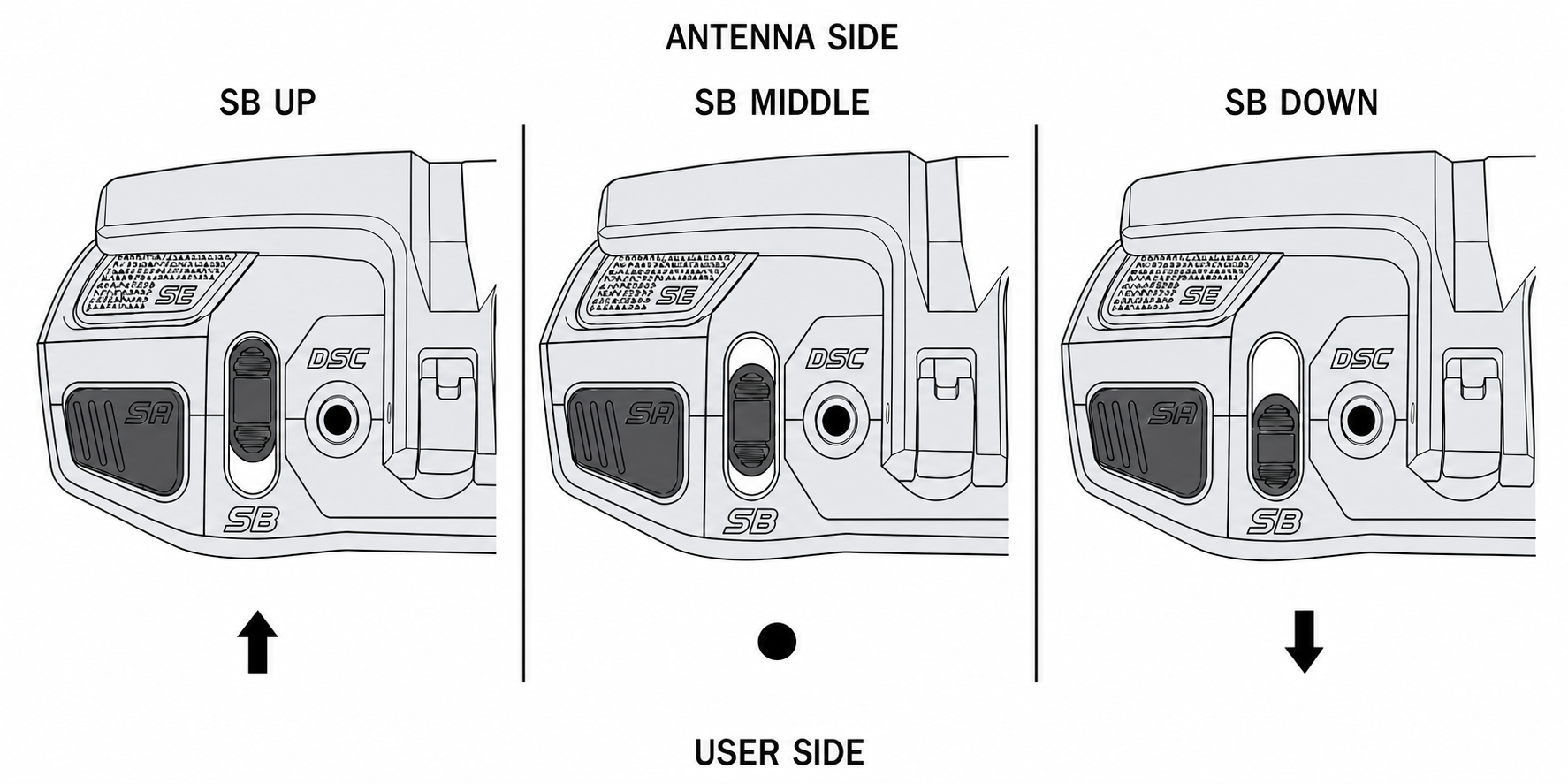
SC selects the main robot state. SB matters only when SC is down.
The image below shows the SB positions from above, with the antenna side at the top and the user side at the bottom.
SB and SC use the same UP, MIDDLE, and DOWN orientation.
SC and SB mode combinations
SC | SB | Screen | Robot action | When to use it |
|---|---|---|---|---|
| Up | Any | Passive | Damping: Resists joint movement without pulling the robot toward a target pose. The robot may sag, and this is not motor-off or E-STOP. | Recommended at startup and for a safe fallback. Control loss, input timeout, or a safety error also requests Damping automatically. |
| Middle | Any | Fixstand | Ready Pose: Moves to the prepared standing pose over about 3 seconds, then actively holds it. | After checking that the area is safe, before entering Velocity or Mimic control. |
| Down | Up | Demo_Mode | Velocity control: Uses the policy configured in ai_sapiens/ai_sapiens_sim2real/config/k1_config.yaml. | When driving the robot with the gimbals. |
| Down | Middle | Demo_Mode | No new mode request; the current mode normally remains active. | Use only as a neutral selection between active requests. It is not Damping or E-STOP. |
| Down | Down | Demo_Mode | Play the selected Mimic motion. | After selecting the desired motion on the main screen. |
SC takes priority, so SB has no effect while SC is up or in the middle.
The recommended flow is: start with SC up, check the surroundings, move SC to the middle and wait for Ready Pose, then move SC down and select the required SB position.
To stop active control, move SC to the middle for Ready Pose or up for Damping.
Do not start with SC down and SB in the middle; the startup safety check does not accept this combination.
Velocity Controls
Move SC down and SB up to enter Velocity control, then use the gimbals as follows:
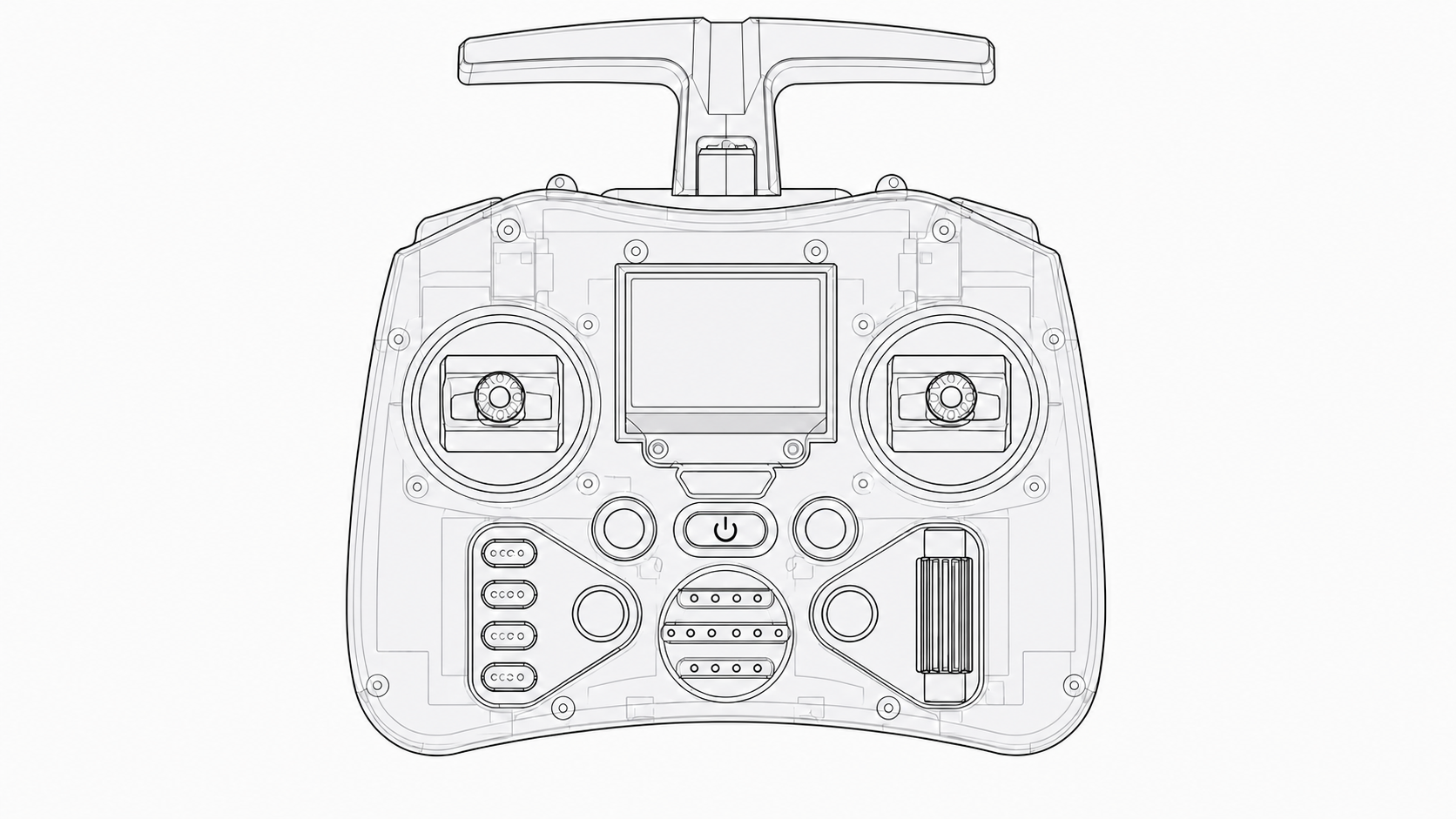
| Gimbal input | Robot movement |
|---|---|
| Left gimbal up / down | Move forward / backward |
| Left gimbal left / right | Move left / right |
| Right gimbal left / right | Turn left / right |
| Right gimbal up / down | Not used for Velocity control |
Move the gimbals gradually and return them to the center to stop the commanded movement.
Selecting and Playing a Mimic Motion
Select the motion on the main screen, then trigger it with SC and SB.
On the RadioMaster Pocket, ENTER means pressing the scroll wheel inward like a button.
- On the main screen, press
ENTERto changeVIEWtoEDIT. - Rotate the scroll wheel to select a Mimic motion.
- Press
ENTERorRTNto return toVIEW. - Move
SCdown, then moveSBdown to play the selected motion.
Holding SB down does not restart the motion.
To play it again, move SB to the middle or up, then move it down again.
If the robot does not play the selected motion, check that SC and SB are both down, UPLINK is OK, and the robot software is running normally.
How to Activate or Deactivate Emergency Stop
The remote controller includes a dedicated Emergency Stop (E-STOP) function using the E-STOP switches. Use this function when you need to stop AI Sapiens immediately from the remote controller.
Always keep enough space around the robot before activating or releasing E-STOP. Release E-STOP only after confirming that the robot and the surrounding area are safe.
If E-STOP is inactive and you are unsure how to use it, move either E-STOP switch in any direction once. The controller will show the activation and deactivation guide without changing the E-STOP state.
E-STOP Switch Guide
The E-STOP instruction overlay shows the activation and deactivation gestures on the controller display.
The E-STOP switches are reserved for the E-STOP gesture and guide display, so they do not adjust the joystick offset.
Activate E-STOP
To activate E-STOP:
- Push both E-STOP switches outward simultaneously: the left switch to the left and the right switch to the right.
- Hold both E-STOP switches outward for at least 0.5 seconds.
While holding the switches, the E-STOP gauge fills on the controller display and the controller beeps several times.
When activation is complete, the display shows ACTIVATED.
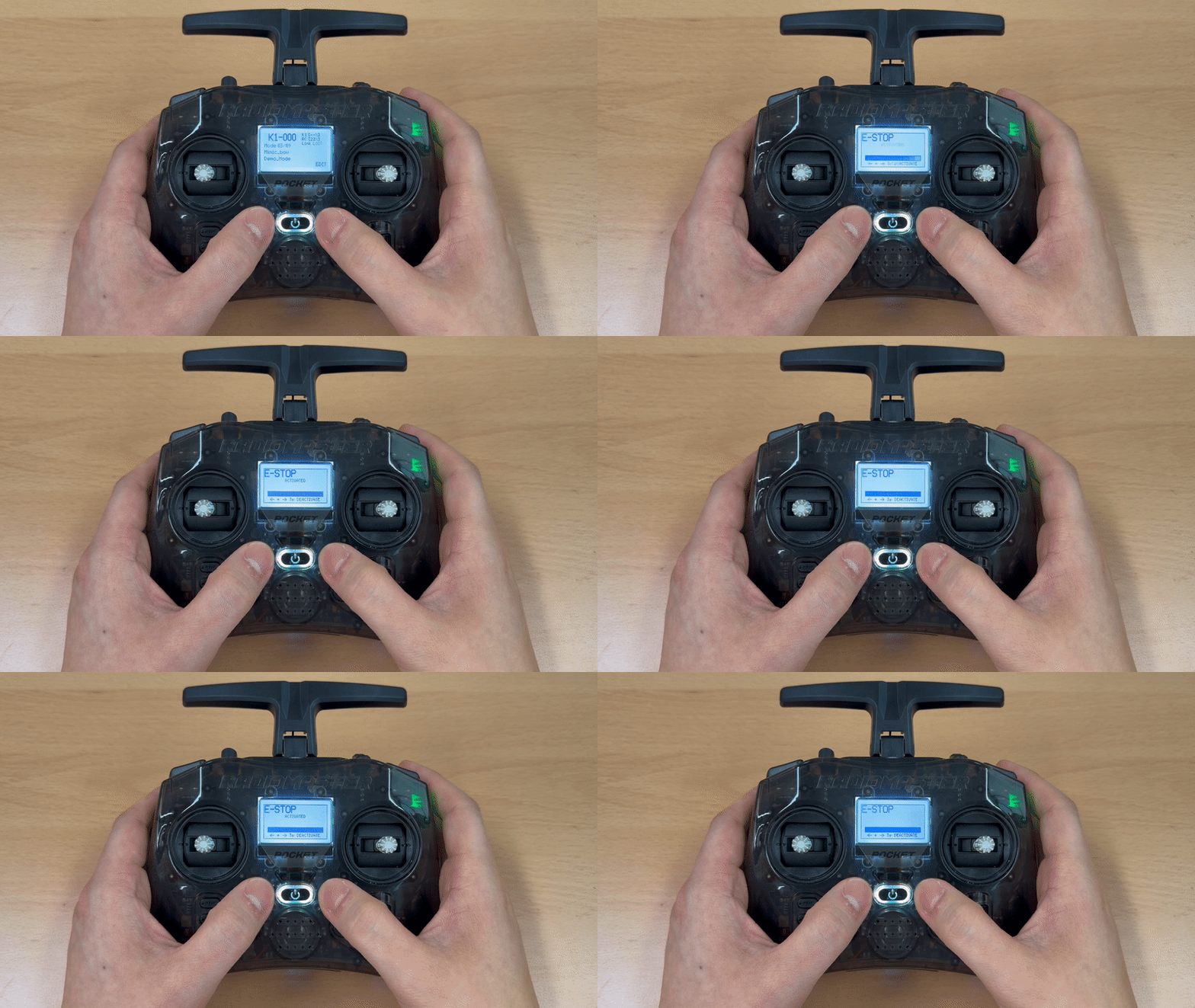
When E-STOP is active, the controller keeps the E-STOP overlay visible.
Deactivate E-STOP
To deactivate E-STOP:
- Make sure it is safe to release the emergency stop.
- Push both E-STOP switches outward simultaneously: the left switch to the left and the right switch to the right.
- Hold both E-STOP switches outward for at least 3 seconds.
While holding the switches, the E-STOP gauge decreases on the controller display.
When deactivation is complete, the display shows DEACTIVATED.
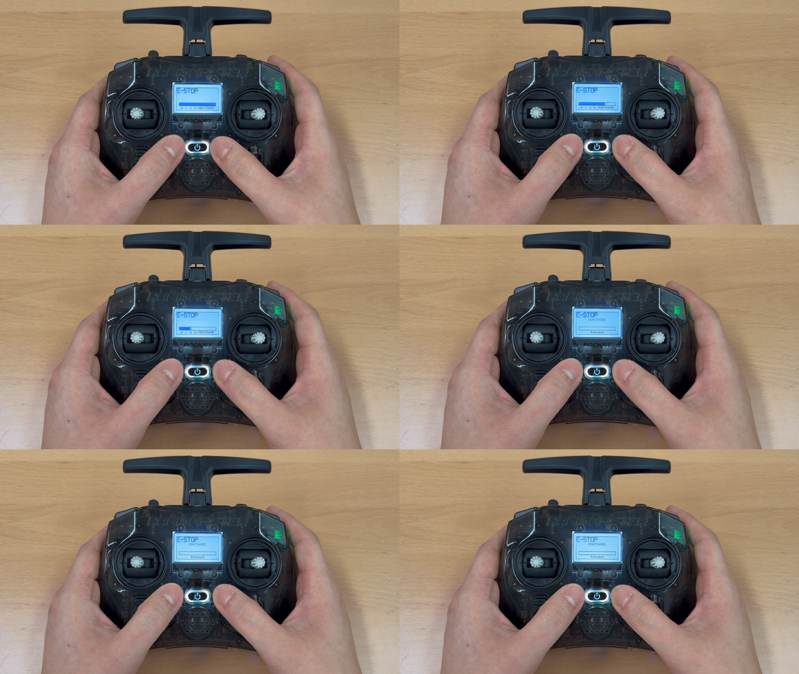
After E-STOP is deactivated, the E-STOP overlay is cleared and the controller returns to the main screen.