Basic Features
Connect DYNAMIXEL
DYNAMIXEL Scan Options
-
Go to
Tools>Optionsor use shortcut keyF4.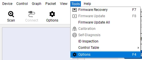
-
Select
Scanfrom the left column menu to display scan options.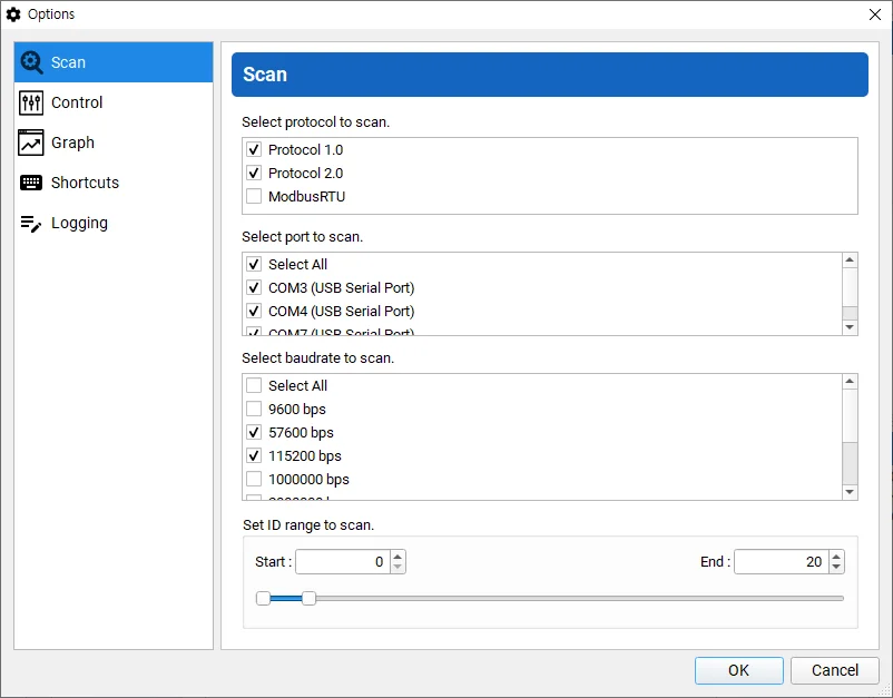
-
Select Protocol Type, communication ports, baudrates, and the range of ID to scan. Click
OKto confirm the selection. Selecting less option reduces time to scan DYNAMIXEL.
Scan DYNAMIXEL
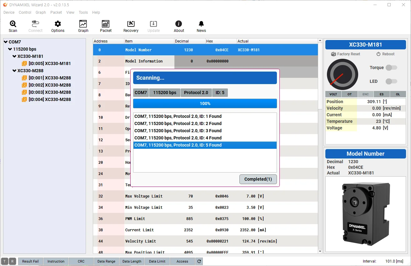
- Go to
Device>Scanto start searching connected DYNAMIXEL's.
NOTE : If Open failed is shown up, please check whether communication port is connected at the Main Toolbar or not, then button Disconnect to avoid port collision.

-
Detected DYNAMIXEL's are listed on the left column.
DYNAMIXEL Control Table
-
Once the
Scanis complete, detected model of DYNAMIXEL will be shown at the device list on the left side pannel. -
Detected DYNAMIXEL's are classified according to communication ports, baudrates, and products. Select a group or device to run the test.

-
Factory Resetbutton in the Sub Menu on the right column will reset DYNAMIXEL to factory status(ID and Baudrate will not be reset).
Rebootbutton will soft reset DYNAMIXEL.
Torqueswitch will toggle the Torque of DYNAMIXEL.
LEDswitch will toggle the LED of DYNAMIXEL.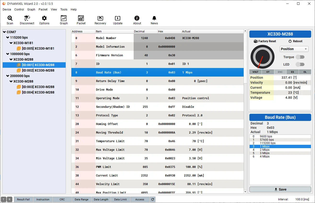
-
Click the
Torquebutton to enable DYNAMIXEL Torque.
-
Select
Goal PositionorGoal Velocityitem in the control table in the middle column.
NOTE: Read the control table of your DYNAMIXEL as the item can be different depending on the model and Operating Mode of the DYNAMIXEL.

- Position controlling interface will appear on the buttom right corner of the program.
WARNING : Please be cautious when changing values as DYNAMIXEL can rotate or move.
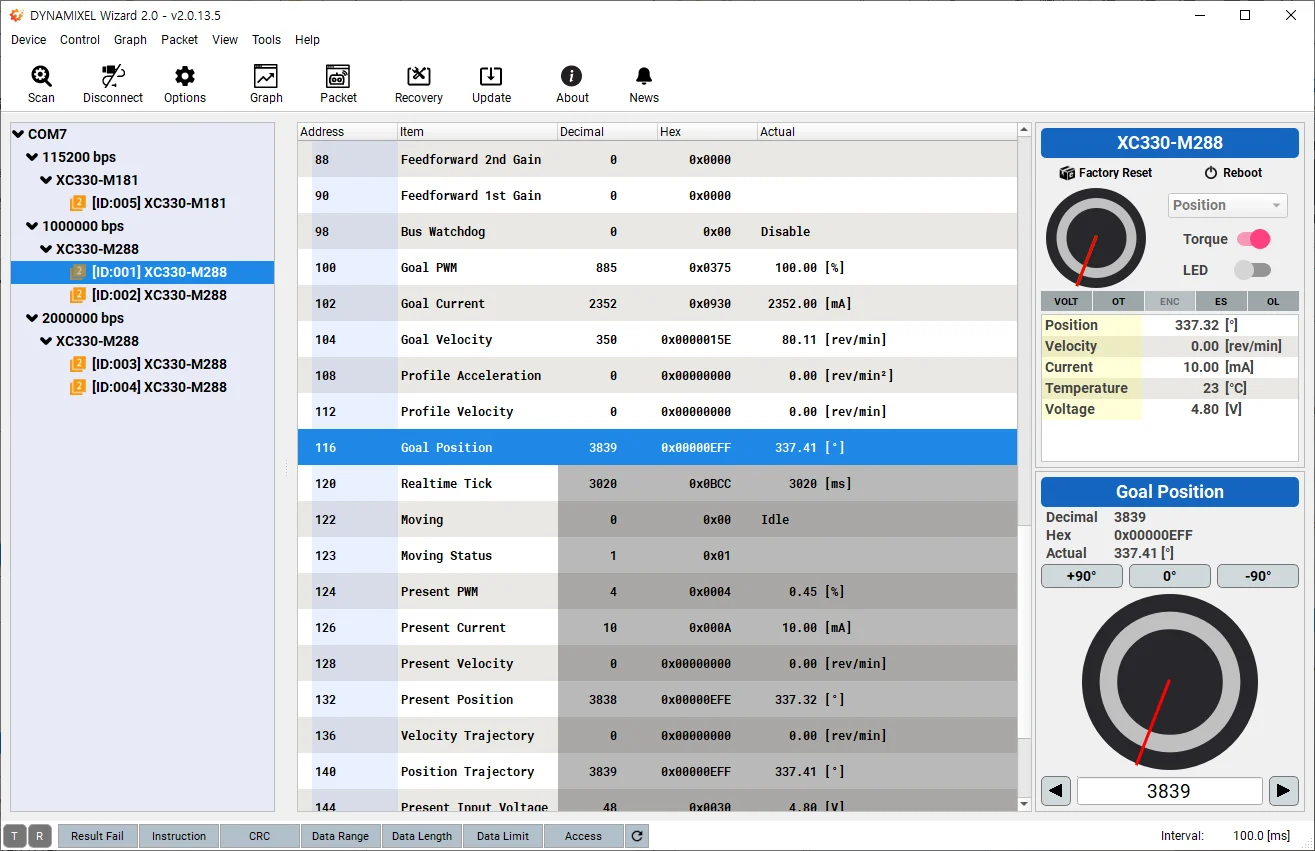
- When selecting
Position controlfrom Operation Mode, you can use a virtual dial controller - Control a horn of DYNAMIXEL by using the controller.
- Input values into the input window.
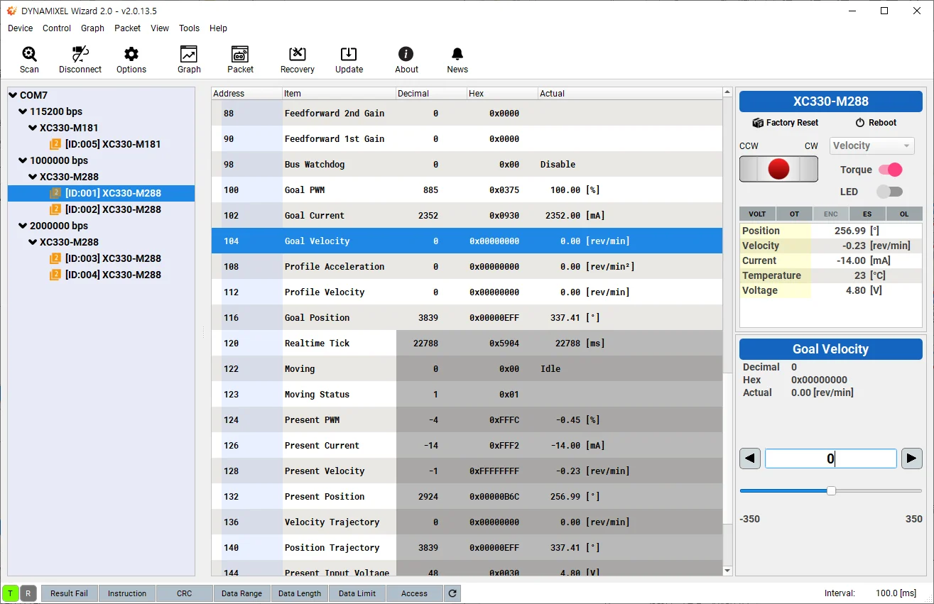
- When selecting
Velocity control/Current control/PWM controlfrom Operation Mode, you can use a virtual joypad. - Move a horn to CW / CCW by using the controller.
- Input values into the input window to increase (or decrease) the speed of a horn of DYNAMIXEL.
- More information on the virtual controller is available at Modifying Control Value
-
Communication Statuson the buttom left corner represents communication status between PC and DYNAMIXEL's. -
The
Packet Statussection indicates the status of response packet from DYNAMIXEL. -
The
Hardware Alarmsection in the Device Status indicates hardware error status of DYNAMIXEL. -
Please refer to e-Manual of each product for more information regarding the Control Table.
-
Below options in the Control Table allow items to be grouped or ungrouped.
- Group : Selected items can be grouped and folded or unfolded.
- Ungroup : Ungroup the selected group.
Graph
Graph Options
-
Go to
Tools>Options -
Select
Graphfrom the left column menu to display scan options.
-
Click
>button to add item. (<can remove item)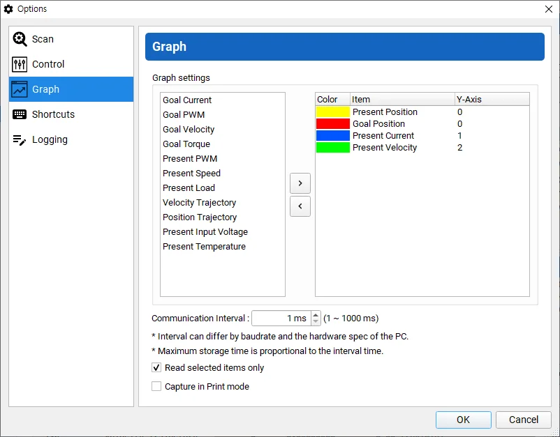
-
Double-click an item, to call
Read Item Settingsbox.
-
Read Item Settingscustomizes a line color with Y axis number.
NOTE: Scale and Offset are no longer appearing at the option box above, from the latest version of software. Adjust these factors at the Graph Window in real time. (See the additional explanation at Y-Axis below)
-
Y-Axis: it adds Y-axis to a selected item. The Maximum is 10.
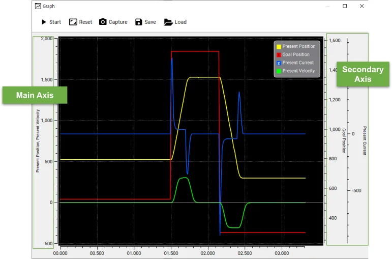
Scale: Adjust scale of axis at the Graph Window (Main Axsis, Secondary Axis) using a mouse wheel.Offset: Adjust Offset by dragging the desired axis up and down at the Graph Window (Main Axsis, Secondary Axis).
- Communication interval can be set between 1 ~ 1000ms. Smaller interval will display refined graph.
NOTE : The actual communication interval can differ by baudrate and the hardware spec of the PC.
- In order to optimize the graph drawing speed, check the option to read selected items only.
NOTE : Checking this option will only refresh selected items in the Control Table.
-
Printing Mode captures your graph with white background.
-
Click
OKto confirm changes.
Start Plotting
-
Go to
View>Graphto display the graph window.
-
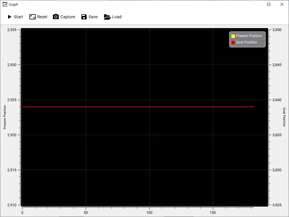
Click
Startbutton in the graph window to start plotting data.
WARNING : If there isn't any detected or connected device, Start button will be disabled. Please scan DYNAMIXEL first.
-
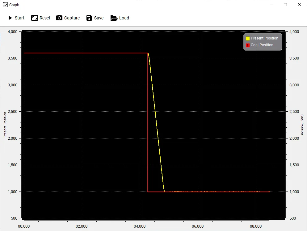
After start plotting, enable Torque first then change
Goal Positionto see howPresent Positiondata is plotted in real time.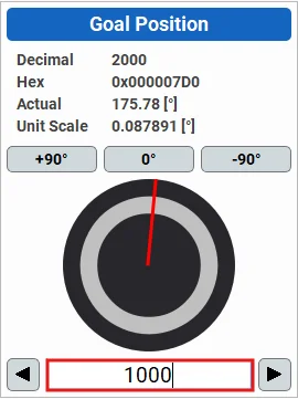
-
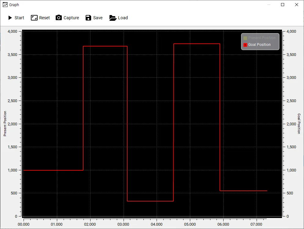
Disable the plotting graph by clicking the certain item on the right side of the graph window.
-
Use the features to control graph window.
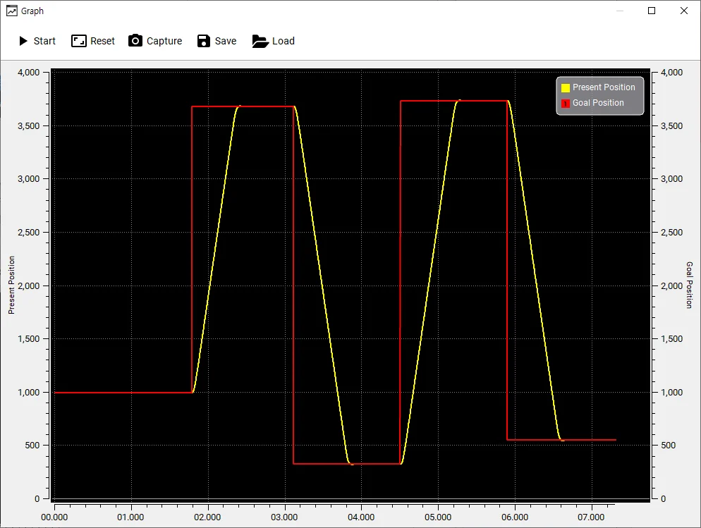
- Start/Stop : Start/Stop plotting
- Reset : Reset zoom level
- Capture : Save current graph window to an image file
- Save : Save plotted data to CSV file
- Load : Load CSV file
- Enable/Disable Item : Click items on the right to toggle visibility
- Zoom : Drag an area to zoom
Shift+Select Area: Zoom In on X axis onlyCtrl+Select Area: Zoom In on Y axis onlyCtrl+Mouse Wheel: Zoom In / Out.
- While running the graph, use
Shift+Mouse Wheelto adjust X axis length from 1 to 10 seconds.
Packet
-
Go to
View>Packetto display the packet window.
-
Set the communication port and baudrate then click
Opento open the port. Once the port is successfully opened, DYNAMIXEL protocol minitoring on the port will begin.
NOTE : If Open failed is shown up, please check whether communication port is connected at the Main Toolbar or not, then button Disconnect to avoid port collision.
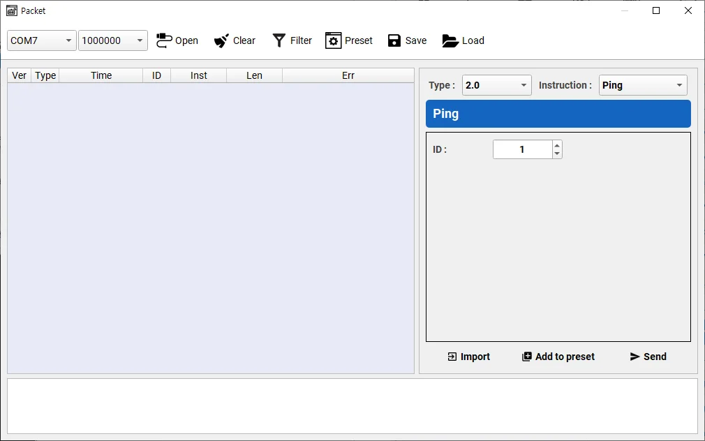
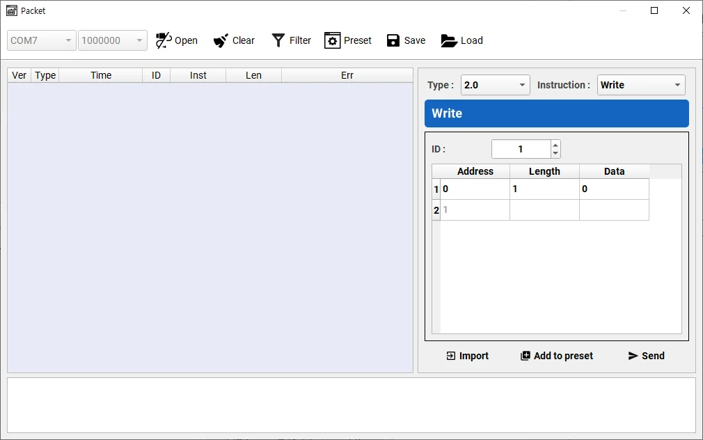
- Select Protocol Type and instruction to use. In this example,
Writeinstruction for Protocol Type2.0is selected.
NOTE : Protocol Type can be different depending on a model of DYNAMIXEL. Confirm Protocol Type of your DYNAMIXEL.
-
Specific data can be written on the instuction as shown below. In this example, LED will be turned on by writing
1to LED control address.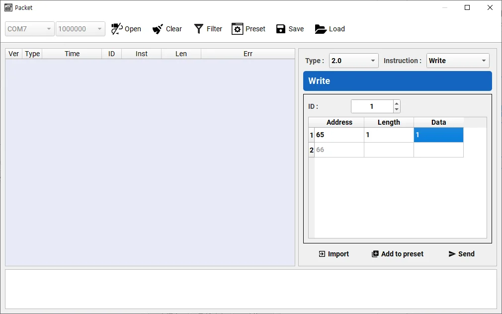
- Control Table address of LED : 65
- Length of the LED data[Byte] : 1
- Value to turn on the LED : 1
-
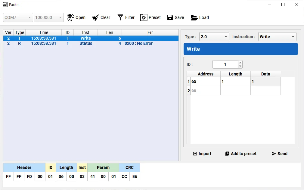
Assembled packet can be found at
Packet Detailssection in the bottom of packet window.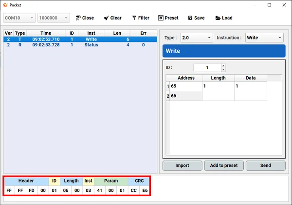
-
Transmit the assembled packet with
Sendbutton.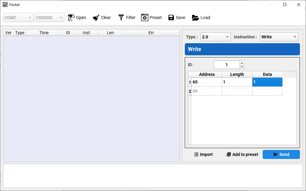
-
Clicking the sent packet shows the detailed packet information.
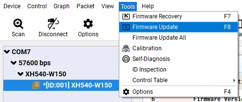
Firmware Update
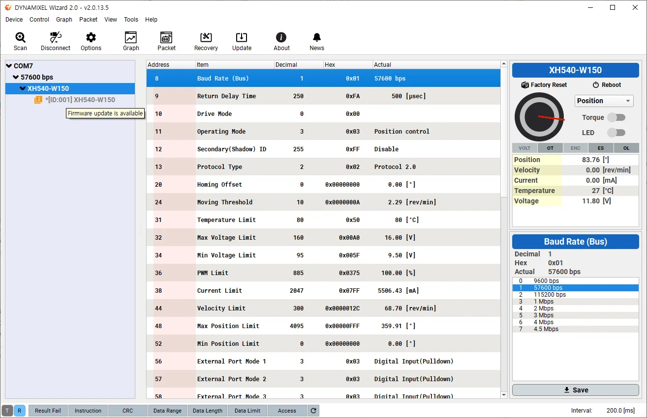
When your connected DYNAMIXEL has a firmware update available an asterisk (*) will be displayed next to the model name on the device list.
When positioning your mouse cursor over the model name, Firmware update is Available will also be displayed as a tooltip.
- Go to
Tools>Firmware Update
NOTE : If no DYNAMIXELS are detected, the Firmware Update option will not be available.
-
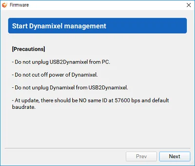
Firmware update will begin with a brief instruction. Please do NOT disconnect or turn off DYNAMIXEL.

-
Click
Nextto begin firmware update. Be careful not to disconnect or turn off DYNAMIXEL.
-
Confirm the firmware update result.

Firmware Update All
-
Go to
Tools>Firmware Update All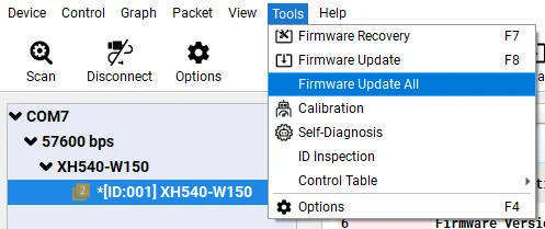
-
Select all or desired DYNAMIXEL's, then click
Nextbutton.
-
Firmware of selected DYNAMIXEL's are updated.

-
Wait until update is completed for all DYNAMIXEL.

Firmware Recovery
-
Go to
Tools>Firmware Recovery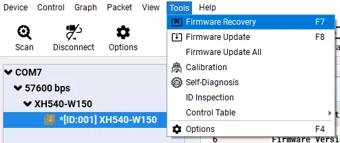
-
Firmware recovery will begin with a brief instruction. Please do NOT disconnect or turn off DYNAMIXEL.
-
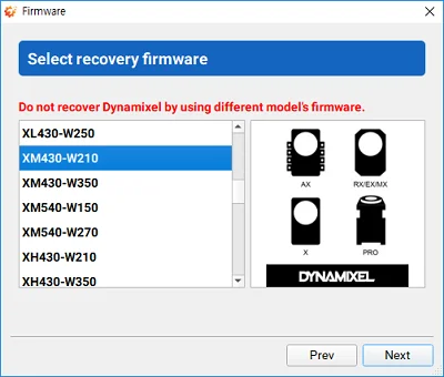
During the firmware recovery mode, DYNAMIXEL Wizard 2.0 cannot identify the model information of DYNAMIXEL, so correct model has to be selected manually. Selecting wrong model can cause malfunction or serious hardware damage.
-
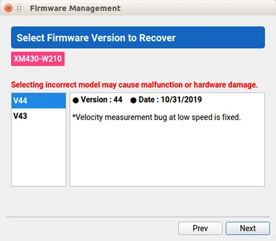
Select a desired firmware version.
-
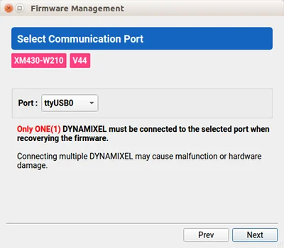
The proper communication port that is connected to DYNAMIXEL has to be selected manually. If the port is in use, it has to be released first.
WARNING : Only one DYNAMIXEL should be connected to the port when recoverying DYNAMIXEL firmware.
-
Toggle the power of DYNAMIXEL to be detected from DYNAMIXEL Wizard 2.0.

-
If DYNAMIXEL is successfully detected, wizard begins firmware recovery. Please do NOT disconnect or turn off DYNAMIXEL.

-
Confirm the firmware recovery result.
