Advanced Features
ID Inspection
DYNAMIXEL Tips | Use ID Inspector to Change Overlapping IDs with Ease
As the DYNAMIXEL can be distinguished by its own ID in packet communication with your main controller, the ID assigned on DYNAMIXEL has to be unique.
If there are overlapping ID in your application, communication between the main controller and DYNAMIXELs or scanning DYANMIXEL via DYNAMIXEL Wizard 2.0 will be failed.
The ID Inspection resolves the overlapping ID although they remain wired. For more details, watch a tutorial video above or read through the following instructions.
Supported DYNAMIXEL
- DYNAMIXEL-X (Firmware v45 or above, For X330 Series: Firmware v46 or above)
- DYNAMIXEL-P (Firmware v12 or above)
- XL-320 is not supported
-
Go to
Tool>ID Inspection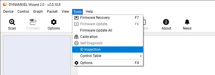
-
Select your right USB port and Baud rates, and click on
Scan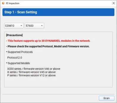
-
Once DYNAMIXEL scan is started, state of scanning DYNAMIXEL is displayed.

Note: Perform Firmware Recovery if you fail to scan any DYNAMIXEL.
-
Click on
Nextfor "ID Setting"

-
Select an item (colored red) and assign new ID from the right box to resolve ID overlapping.
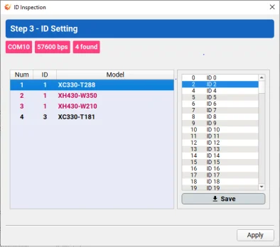
Note : If you select any item in the list, the DYNAMIXEL will blink once.
-
If new ID are saved to the items of DYNAMIXEL, it will be colored green. Once completed, click on
Apply.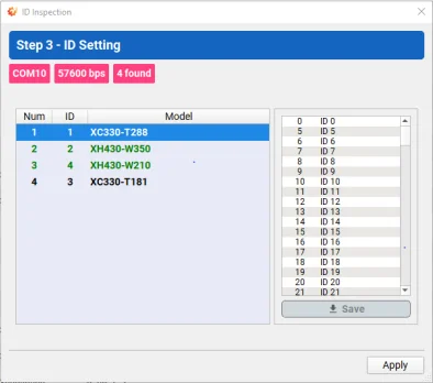
-
Click on
Finishto exit theID Inspectionwindow.
-
Confirm the DYNAMIXEL Wizard 2.0 scans DYNAMIXELs successfully.

Backup and Restore
DYNAMIXEL Tips | EEPROM and RAM Data Restoring Using Backup Funcion
Data in both EEPROM and RAM (Specific items only) can be stored inside DYNAMIXEL using Backup function.
This can be useful if the DYNAMIXEL are reset after the Firmware Recovery or any situation in data reset.
The stored data by backup can be restored in using Restore EEPROM.
See the available items in Control Table for data backup,
- All Data in EEPROM
- Velocity P.I Gains
- Position P.I.D Gains
- Feedforward 1st & 2nd Gains
- Profile Acceleration
- Profile Velocity
- Indirect Addresses (Except DYNAMIXEL-P Series)
Note: Be sure to set the Restore RAM bit of the Startup Configuration(60) address in order to restore the RAM data on startup.
Supported DYNAMIXEL
- DYNAMIXEL-X (Firmware v45 or above, For X330 Series: Firmware v46 or above)
- DYNAMIXEL-P (Firmware v12 or above)
- XL-320 is not supported
Control Table Backup
-
Connect and Scan DYNAMIXEL.
-
Make sure to turn off the Torque of DYNAMIXEL. Otherwise, backup will fail.

-
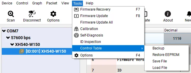
Select
Tool>Control Table>Backup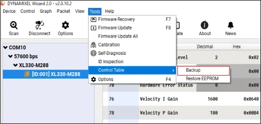
-
Check if the
Backup Ready(147)address is set to1after backup.
Restoring EEPROM Area
-
Go to
Tool>Control Table>Restore EEPROM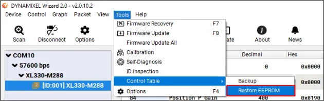
-
DYNAMIXEL will be rebooted and restore the EEPROM settings.
Restoring RAM Area
-
Set the Restore RAM bit of the
Startup Configurationas below.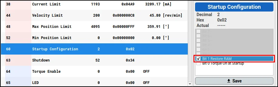
-
The data in specific RAM area(listed below) will be restored when DYNAMIXEL is rebooted.
- Velocity P.I Gains
- Position P.I.D Gains
- Feedforward 1st & 2nd Gains
- Profile Acceleration
- Profile Velocity
- Indirect Addresses (Except for DYNAMIXEL-P Series)
Save and Load Backup File
Save and Load backup data of EEPROM field as .ctd file. Utilizing "Save and Load Backup File" reduces the consuming time tasks of DYNAMIXEL configuration, and lowers the possibility of configuration error.
NOTE: Saved backup file(.cd) can be used between the same DYNAMIXEL models.
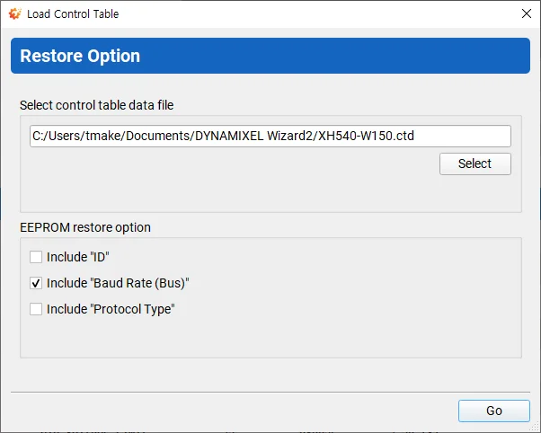
When loading backup data from .ctd file, it provides restoring options to ignore restoring particular data at EEPROM field.
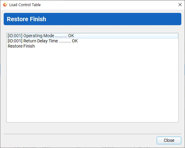
The resulting log shows the restored item.
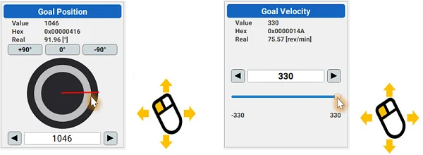
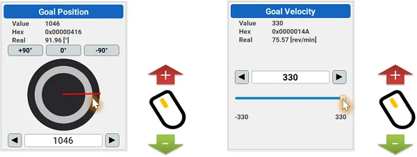
Modifying Control Values
-
Drag or slide the interface (Moderately changes values)
-
Mouse wheel scroll (Slightly changes value)
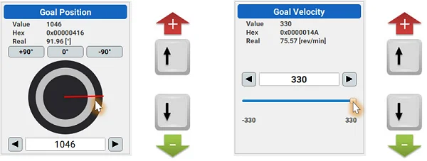
-
Directional keys (Finely changes value)
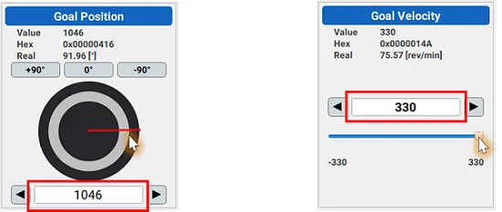
-
Enter the value
NOTE : Press Enter key to apply the value.
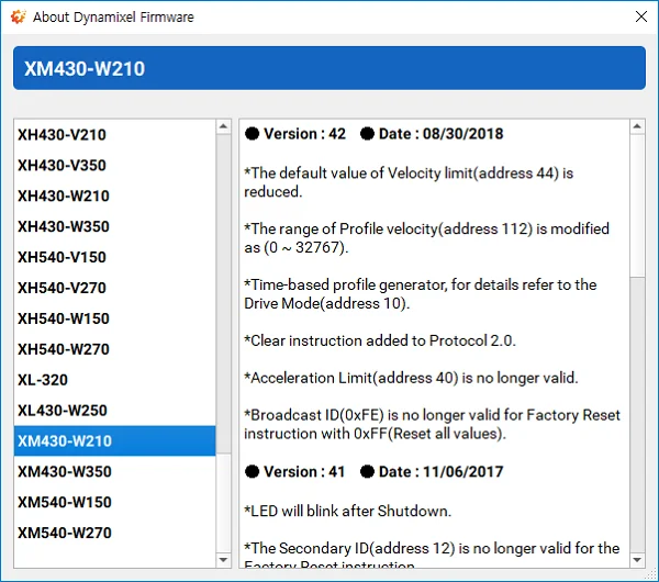
Firmware Information
Firmware version, release date, update note can be found here.
-
Go to
Help>About Dynamixel Firmware
-
Firmware version, release date, update note of the selected DYNAMIXEL can be found.
Calibration
If the horn is misaligned after gear set replacement or reassembly, please perform calibration.
-
Go to
Tool>Calibration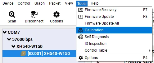
NOTE: Calibration itme will be disabled at the menu for non-supported DYNAMIXEL such as AX Series
WARNING : Only one DYNAMIXEL has to be connected to the port when calibrating DYNAMIXEL.
-
Calibration will begin with a brief instruction.

-
Toggle the power of DYNAMIXEL to be detected from DYNAMIXEL Wizard 2.0.

-
If DYNAMIXEL is successfully detected, calibration firmware will start being installed. Please do NOT disconnect or turn off DYNAMIXEL.


-
Calibrate the first position.

-
Calibrate the second position.

-
Calibrate the third position.

-
Calibrate the fourth position.

-
Clibration is completed.

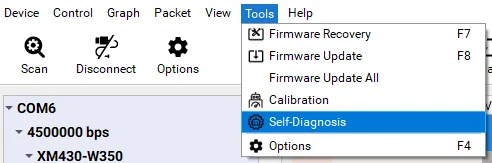
Self Diagnosis
In order to find error in DYNAMIXEL, self diagnosis can be performed.
- Go to
Tool>Self-Diagnosis
NOTE : Self-Diagnosis item will be disabled at the menu for non-suppored DYNAMIXEL such as RX Series
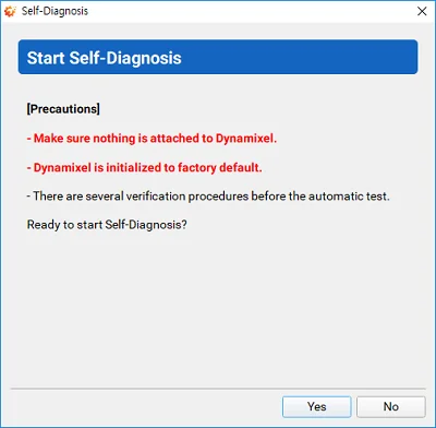
- Self diagnosis will begin with a brief instruction.
WARNING : DYNAMIXEL will be factory reset during self diagnosis.
-
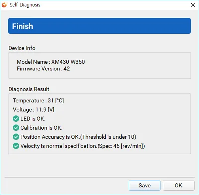
Confirm the model name and firmware version of DYNAMIXEL to perform diagnosis.

-
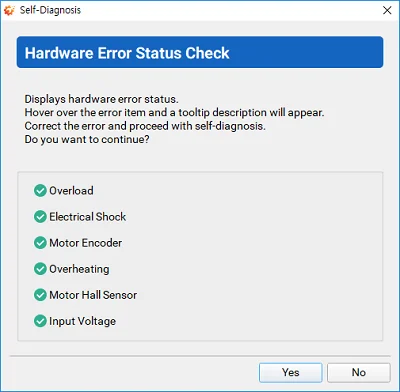
Check the hardware error status of DYNAMIXEL.
-
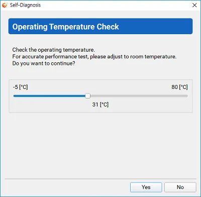
Check the operating temperature of DYNAMIXEL.
-
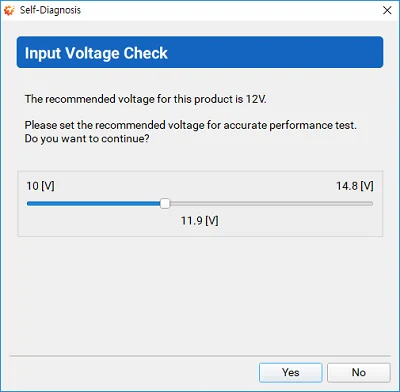
Check the input voltage of DYNAMIXEL.
-
Check if the LED on DYNAMIXEL is blinking.

-
Check if DYNAMIXEL horn is at the center.

-
Proceed to performance test.
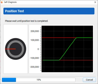
Position Test : Goal Position represents red line and Present Position represents green line.
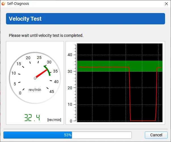
Velocity Test : Safe area represents a green zone.
-
Confirm the self diagnosis result.
Graph Optimization
In order to use the minimum communication interval(1 [ms]), please follow the instruction below.
USB Latency Setting
Windows
-
Open
Device Manager. Go toPortsitem and right click on the relative serial port to selectProperties.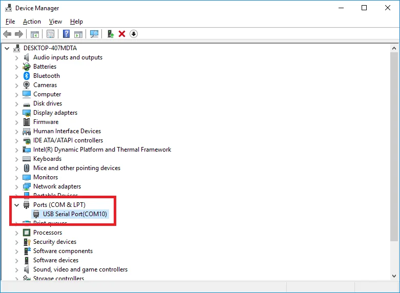
-
In the Properties window, go to
Port Settingstab and clickAdvancedbutton.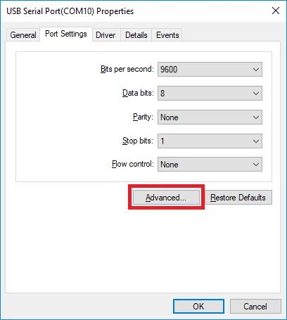
-
Set the
Latency Timer (msec)to1msand clickOKto confirm the change.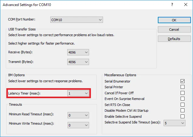
Linux
- Execute below commands to configure the
latency_timerto1ms.
# cat /sys/bus/usb-serial/devices/ttyUSB0/latency_timer
16
# echo 1 > /sys/bus/usb-serial/devices/ttyUSB0/latency_timer
# cat /sys/bus/usb-serial/devices/ttyUSB0/latency_timer
1
DYNAMIXEL Setting
-
Open the graph options window to set
Intervalto1ms. Then, mark on theRead only selected item for Speedoption.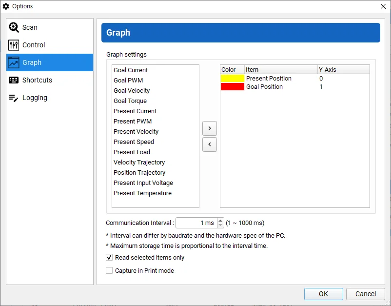
-
Set the baudrate of DYNAMIXEL to maximum and set
Return Delay Timeto0.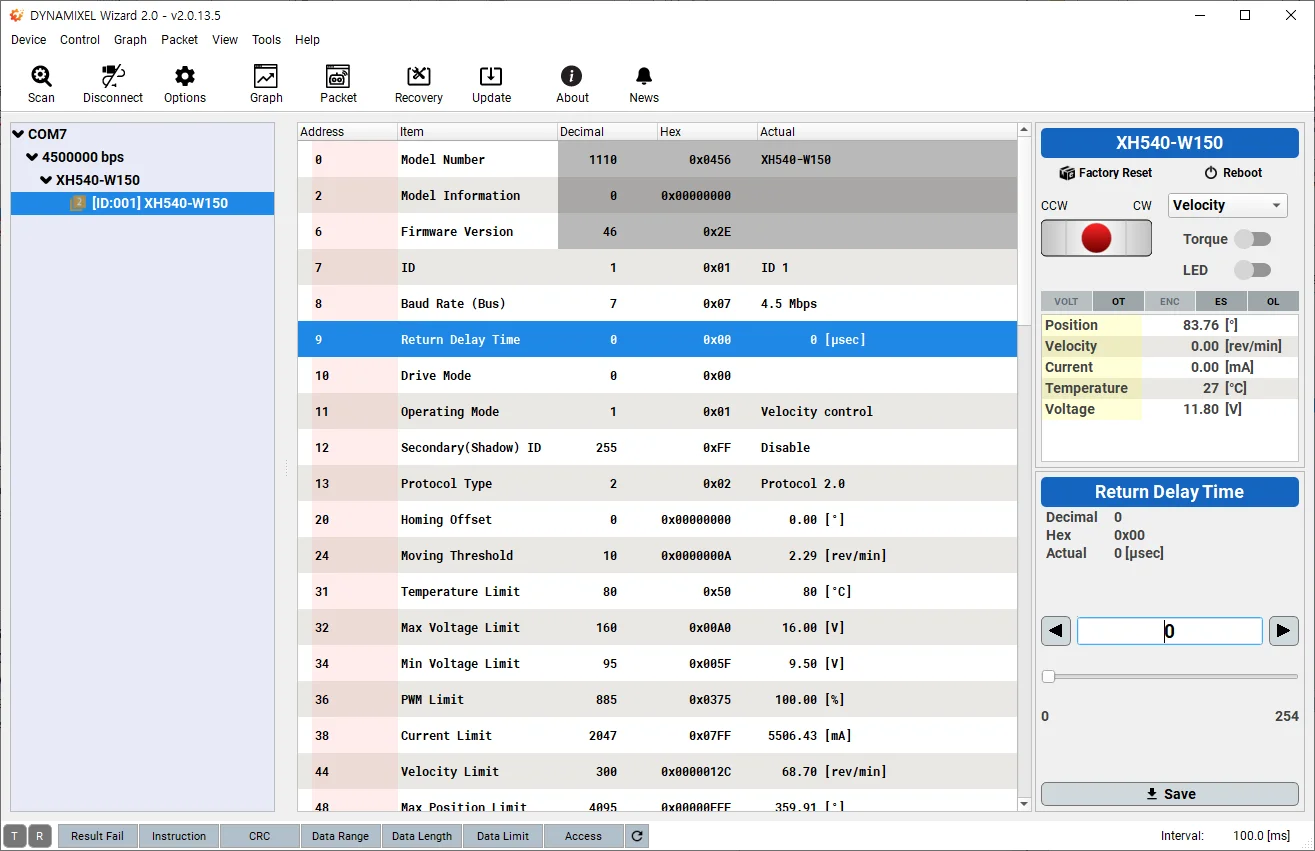
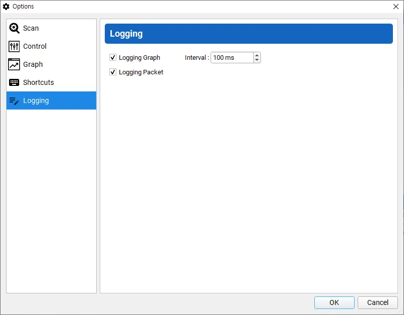
Logging
Save a log file of a packet information in DYNAMIXEL Wizard 2.0.
-
In case of Graph, it saves the most nearest, the minimum, the maximum and the average value at your set interval.
-
In case of Packet, it saves every monitored packets.
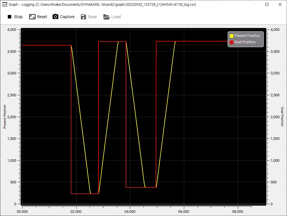
Graph Logging
Once starting the graph, the logging file is saved under Documents/DYNAMIXEL Wizard2/graph/
The whole path to save can be found at a title bar.
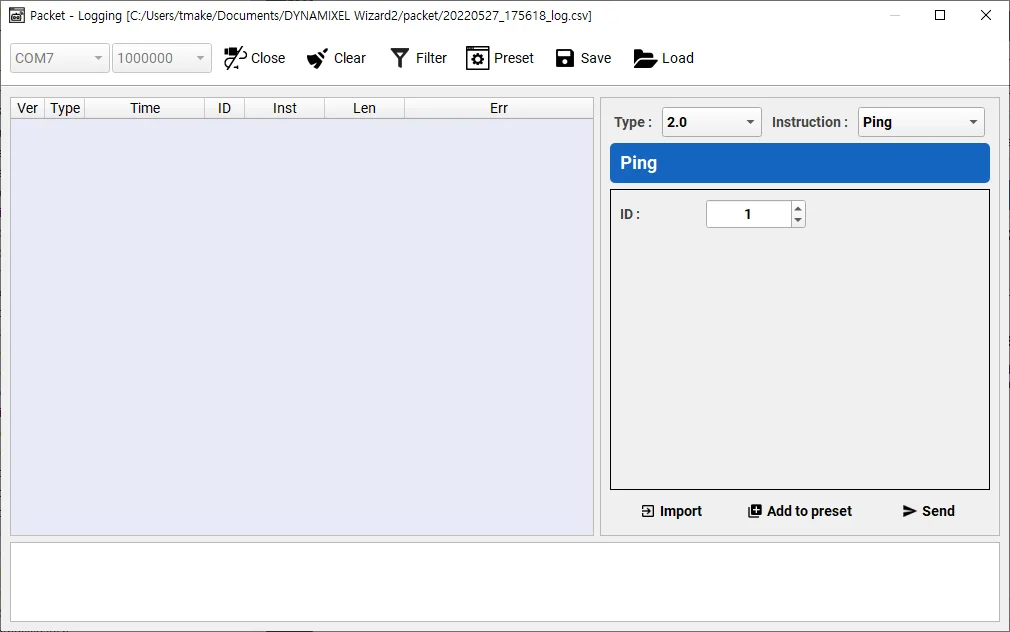
Packet Logging
Once opening the communication port, the logging file is saved under Documents/DYNAMIXEL Wizard2/packet/
The whole path to save can be found at a title bar.