- Servo library is used to drive RC servo for RC.
- RC Servo Library uses OpenCM9.04 hardware timer and can be used by connecting to PWM output pin.
- A2 to D14 pins are PWM output pins.
- Be careful when using Servo library because other functions using hardware timer can not be used at the same time.
- See the list below for the hardware and channels used.
{GPIOA, GPIO_PIN_0,   &hADC1,   ADC_CHANNEL_0 , &hTIM2 ,   TIM_CHANNEL_1, 2       },  // 2
{GPIOA, GPIO_PIN_1,   &hADC1,   ADC_CHANNEL_1 , &hTIM2 ,   TIM_CHANNEL_2, 3       },  // 3
{GPIOA, GPIO_PIN_2,   &hADC1,   ADC_CHANNEL_2 , &hTIM2 ,   TIM_CHANNEL_3, 4       },  // 4
{GPIOA, GPIO_PIN_3,   &hADC1,   ADC_CHANNEL_3 , &hTIM2 ,   TIM_CHANNEL_4, 5       },  // 5
{GPIOA, GPIO_PIN_6,   &hADC1,   ADC_CHANNEL_6 , &hTIM3 ,   TIM_CHANNEL_1, 6       },  // 6
{GPIOA, GPIO_PIN_7,   &hADC1,   ADC_CHANNEL_7 , &hTIM3 ,   TIM_CHANNEL_2, 7       },  // 7
{GPIOB, GPIO_PIN_0,   &hADC1,   ADC_CHANNEL_8 , &hTIM3 ,   TIM_CHANNEL_3, 8       },  // 8
{GPIOB, GPIO_PIN_1,   &hADC1,   ADC_CHANNEL_9 , &hTIM3 ,   TIM_CHANNEL_4, 9       },  // 9

{GPIOA, GPIO_PIN_8,   NULL,     NO_ADC        , &hTIM1 ,   TIM_CHANNEL_1, 10      },  // 10
{GPIOA, GPIO_PIN_9,   NULL,     NO_ADC        , &hTIM1 ,   TIM_CHANNEL_2, 11      },  // 11
{GPIOA, GPIO_PIN_10,  NULL,     NO_ADC        , &hTIM1 ,   TIM_CHANNEL_3, 12      },  // 12
{GPIOB, GPIO_PIN_8,   NULL,     NO_ADC        , &hTIM4 ,   TIM_CHANNEL_3, 13      },  // 13
{GPIOB, GPIO_PIN_9,   NULL,     NO_ADC        , &hTIM4 ,   TIM_CHANNEL_4, 14      },  // 14 LED
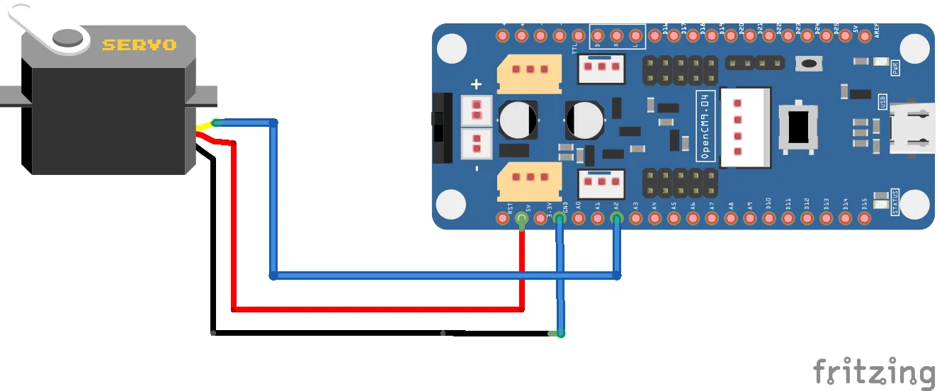
Connection
Arduino code
This is an example of a Servo library and uses the A2 pin of OpenCM9.04. The range of the input value is 0 to 180 degrees.
#include <Servo.h>

Servo myservo;  // create servo object to control a servo

void setup() {
  myservo.attach(A2);  // attaches the servo on pin 2 to the servo object
}

void loop() {
  myservo.write(0);                    // sets the servo position according to the scaled value
  delay(1000);                         // waits for the servo to get there
  myservo.write(180);                  // sets the servo position according to the scaled value
  delay(1000);                         // waits for the servo to get there
}