Y Series
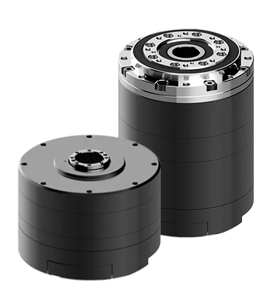
DYNAMIXEL-Y is ROBOTIS’ industrialized premium robot actuator solution for full scale Robots
Product Lineup
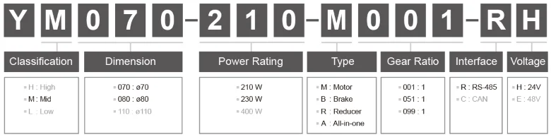
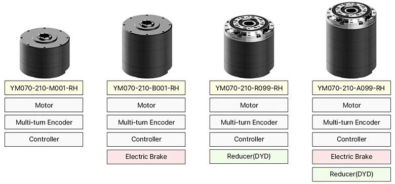
DYNAMIXEL-Y Lineups
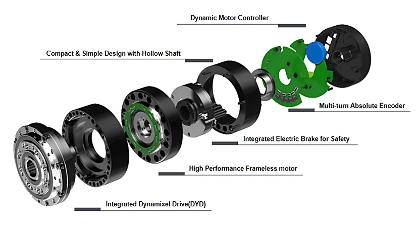
Features
- High Performance Frameless motor
- Multi-turn Absolute Encoder
- Integrated Electric Brake for Safety
- Integrated Dynamixel Drive(DYD)
- Compact & Simple Design with Hollow Shaft
- Dynamic Motor Controller

Key Specifications
YM070
| Model | Dimensions [mm] | Weight [g] | Gear Ratio [R] | Continuous Torque [N.m] | Maximum Torque [N.m] | Input Voltage [V] | Resolution [pulse/rev] | Type |
|---|---|---|---|---|---|---|---|---|
| YM070-210-M001-RH | Ø70 x 50.9 | 340 | - | 0.32 | 0.64 | 24 | 524,288 | Motor |
| YM070-210-B001-RH | Ø70 x 71.0 | 530 | - | 0.32 | 0.64 | 24 | 524,288 | Motor, Brake |
| YM070-210-R051-RH | Ø70 x 71.1 | 790 | 51:1 | 8.2 | 16.3 | 24 | 26,738,688 | Motor, Reducer |
| YM070-210-R099-RH | Ø70 x 71.1 | 790 | 99:1 | 14.6 | 31.7 | 24 | 51,904,512 | Motor, Reducer |
| YM070-210-A051-RH | Ø70 x 91.2 | 980 | 51:1 | 8.2 | 16.3 | 24 | 26,738,688 | Motor, Reducer, Brake |
| YM070-210-A099-RH | Ø70 x 91.2 | 980 | 99:1 | 14.6 | 31.7 | 24 | 51,904,512 | Motor, Reducer, Brake |
YM080
| Model | Dimensions [mm] | Weight [g] | Gear Ratio [R] | Continuous Torque [N.m] | Maximum Torque [N.m] | Input Voltage [V] | Resolution [pulse/rev] | Type |
|---|---|---|---|---|---|---|---|---|
| YM080-230-M001-RH | Ø80 x 54.1 | 530 | - | 0.62 | 1.24 | 24 | 524,288 | Motor |
| YM080-230-B001-RH | Ø80 x 76.1 | 890 | - | 0.62 | 1.24 | 24 | 524,288 | Motor, Brake |
| YM080-230-R051-RH | Ø80 x 78.1 | 1,200 | 51:1 | 15.8 | 31.6 | 24 | 26,738,688 | Motor, Reducer |
| YM080-230-R099-RH | Ø80 x 78.1 | 1,200 | 99:1 | 26.0 | 61.4 | 24 | 51,904,512 | Motor, Reducer |
| YM080-230-A051-RH | Ø80 x 100.1 | 1,550 | 51:1 | 15.8 | 31.6 | 24 | 26,738,688 | Motor, Reducer, Brake |
| YM080-230-A099-RH | Ø80 x 100.1 | 1,550 | 99:1 | 26.0 | 61.4 | 24 | 51,904,512 | Motor, Reducer, Brake |
Communication Circuit
UART Connection Circuit Diagram
To control DYNAMIXEL-Y with a custom controller, the UART signal must be half-duplex serial. The recommended circuit diagram to convert between full and half duplex serial communications is shown below:
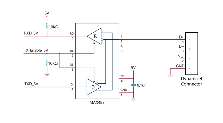
Note: The circuit above is suitable for MCUs that use a 5V logic level or when the IO is 5V tolerant. For other cases, use a Level Shifter to match the voltage level of your controller with DYNAMIXEL's 5v logic level.
The above circuit is integrated into ROBOTIS' DYNAMIXEL controllers. In the provided circuit diagram, the direction of the TxD and RxD signals is determined based on the level of TX_Enable_5V as indicated below.
- If TX_Enable_5V =High : The TxD signal is transferred to D+ and D-
- If TX_Enable_5V =Low : The D+ and D- signals are transferred to RxD
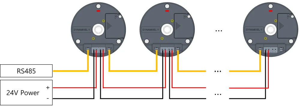
Cable Connection
The pin configuration of the DYNAMIXEL-Y connector is shown below.
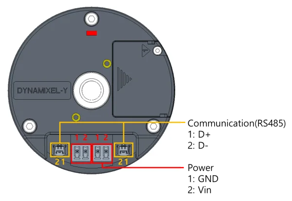
WARNING: Ensure that you adhere to the correct pin arrangement during DYNAMIXEL installation. Incorrectly connected DYNAMIXEL servos may be severely damaged.