P Series
Product Lineup
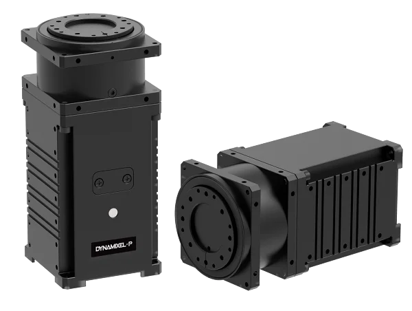
DYNAMIXEL-P Lineups
NOTE: DYNAMIXEL PRO+ is renamed as DYNAMIXEL-P.
-
Revised Date: Jan 2th, 2020.
-
Revised Model Name: See the following table.
Previous New H54P-200-S500-R PH54-200-S500-R H54P-100-S500-R PH54-100-S500-R H42P-020-S300-R PH42-020-S300-R M54P-060-S250-R PM54-060-S250-R M54P-040-S250-R PM54-040-S250-R M42P-010-S260-R PM42-010-S260-R
-
Integrated robot-driving device : Contains all necessary features for robot joints integrated into a single module.

-
Strong and durable reduction cycloid gearing : DYNAMIXEL-P implements removable reduction cycloid gears. Small and lightweight cycloids allow a high-ratio reduction gear device. Also cycloid gears are more resistant to vibrations and impacts resulting in minimal backlash.
-
Variety of models : DYNAMIXEL-P motor, reduction ratio, communications type, etc have been accommodated to meet various price ranges. The user is able to choose the most proper DYNAMIXEL-P model necessary for the robot.
-
Variety of control algorithms : DYNAMIXEL-P adopts position, velocity, and electrical current control algorithms. The user can control these 3 aspects in any combination and properly tune the robot. DYNAMIXEL-P provides a graph illustrating the relationship between electrical current and torque. This feature is useful for torque control via current control.
-
Precision control : With a maximum of 1,003,846 resolution, users can control about 0.0004 degrees per unit allowing for high-precision control.
Key Specifications
| Model | Dimensions(mm) | Weight | Resolution | Motor |
|---|---|---|---|---|
| PH54-200-S500-R | 54 x 126 x 54 | 855g | 1,003,846 | BLDC (Maxon) |
| PH54-100-S500-R | 54 x 108 x 54 | 740g | 1,003,846 | BLDC (Maxon) |
| PH42-020-S300-R | 42 x 84 x 42 | 340g | 607,500 | Coreless (Maxon) |
| PM54-060-S250-R | 54 x 126 x 54 | 855g | 502,834 | BLDC (Maxon) |
| PM54-040-S250-R | 54 x 108 x 54 | 710g | 502,834 | BLDC (Maxon) |
| PM42-010-S260-R | 42 x 72 x 42 | 270g | 526,374 | Coreless (Maxon) |
Communication Circuitry
Connection to UART
To control DYNAMIXEL-P with a custom made Main Controller, the signal of Main Controller UART should be converted into RS-485 signal. The following is a recommended conversion circuit diagram.
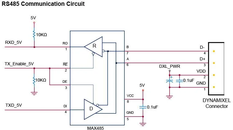
NOTE: Above circuit is designed for 5V or 5V tolerant MCU. Otherwise, use a Level Shifter to match the voltage of MCU.
The power is supplied via Pin1(-) and Pin2(+) of DYNAMIXEL. (The above circuit is built into DYNAMIXEL-only controllers)
In the above circuit diagram, the direction of data signal of TxD and RxD in the TTL Level is determined according to the level of TX_Enable_5V as follows:
- If
TX_Enable_5V= High : TheTXD_5Vsignal is transferred toD+andD-. - If
TX_Enable_5V= Low : TheD+andD-signals are transferred toRXD_5V.
Pin Arrangement
Connector pin arrangement is shown below.
DYNAMIXEL-P has two 4-pin connectors arranged in pin-2-pin configuration.
In this arrangement there's no priority in the connector order and DYNAMIXEL-P can be driven like the MX-series.
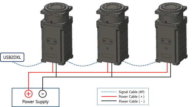
Additionally there is a 2-pin connector dedicated for power input for high-current operations.
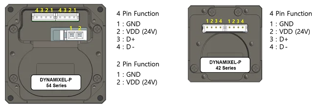
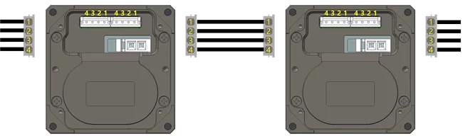
WARNING : When wiring please pay attention to the pin arrangement. Incorrectly connected DYNAMIXEL-P may be damaged severely.
Confirmation of Connection
The LED of DYNAMIXEL-P flickers once if the power is supplied to DYNAMIXEL-P properly via wiring.
Drawing
The output horn has been redesigned. Please refer to below comparisons between DYNAMIXEL PRO and DYNAMIXEL-P.
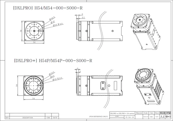
Please also checkout ROBOTIS Download Center for software applications, 3D/2D CAD, and other useful resources!