
MX-12W
Specifications
| Item | Specifications |
|---|---|
| MCU | ARM CORTEX-M3 (72 [MHz], 32Bit) |
| Position Sensor | Contactless absolute encoder (12Bit, 360 [°]) Maker : ams(www.ams.com), Part No : AS5045 |
| Motor | Cored |
| Baud Rate | 7,834 [bps] ~ 3 [Mbps] |
| Control Algorithm | PID CONTROL |
| Resolution | 4096 [pulse/rev] |
| Operating Modes | Joint Mode (0 ~ 360 [°]) Endless Turn Multi-turn |
| Weight | 55.0 [g] |
| Dimensions (W x H x D) | 32 x 50 x 40 [mm] |
| Gear Ratio | 32 : 1 |
| Stall Torque | 0.2 [N.m] (at 12.0 [V], 1.4 [A]) |
| No Load Speed | 470 [rev/min] (at 12.0 [V]) |
| Operating Temperature | -5 ~ +70 [°C] |
| Input Voltage | 10.0 ~ 14.8 [V] (Recommended : 12.0 [V]) |
| Command Signal | Digital Packet |
| Protocol Type | Half Duplex Asynchronous Serial Communication (8bit, 1stop, No Parity) |
| Physical Connection | TTL Level Multidrop Bus(Daisy Chain Type Connector) |
| ID | 253 ID (0 ~ 252) |
| Feedback | Position, Temperature, Load, Input Voltage, etc |
| Case Material | Engineering Plastic |
| Gear Material | Engineering Plastic |
| Standby Current | 60 [mA] |
![]()
DANGER (Ignoring these warnings may cause serious injury or death)
- Never place items containing water, flammables/open flames, or solvents near the product.
- Never place fingers, arms, toes, and other body parts near product during operation.
- Cease operation and remove power from the product if the product begins to emit strange odors, noises, or smoke.
- Keep product out of reach of children.
- Check input polarity before installing or energizing wiring or cables.
![]()
CAUTION (Ignoring these warnings may cause mild injury or damage to the product)
- Always comply with the product's offical operating environment specifications including input voltage, current, and operating temperature.
- Do not insert blades or other sharp objects during product operation.
![]()
ATTENTION (Ignoring these warnings may cause minor injury or damage to the product)
- Do not disassemble or modify the product.
- Do not drop the product or apply strong impacts.
- Do not connect or disconnect DYNAMIXEL cables while power is being supplied.
Control Table
The Control Table is a data structure used by DYNAMIXEL actuators to manage the state of the device. Users can read data registers to get information about the status of the device with Read Instruction Packets, and modify data registers to control the device with Write Instruction Packets.
Control Table, Data, Address
The Control Table is a structure that consists of multiple Data fields to store status or to control the device. Users can check current status of the device by reading a specific Data from the Control Table with Read Instruction Packets. WRITE Instruction Packets enable users to control the device by changing specific Data in the Control Table. The Address is a unique value when accessing a specific Data in the Control Table with Instruction Packets. In order to read or write data, users must designate a specific Address in the Instruction Packet. Please refer to DYNAMIXEL Protocol 1.0 for more details about Instruction Packets.
Area (EEPROM, RAM)
The Control Table is divided into 2 Areas. Data in the RAM Area is reset to initial values when the power is reset(Volatile). On the other hand, data in the EEPROM Area is maintained even when the device is powered off(Non-Volatile).
Size
The Size of data varies from 1 ~ 2 bytes depend on their usage. Please check the size of data when updating the data with an Instruction Packet. For data larger than 2 bytes will be saved according to Little Endian.
Access
The Control Table has two different access properties. 'RW' property stands for read and write access permission while 'R' stands for read only access permission. Data with the read only property cannot be changed by the WRITE Instruction. Read only property('R') is generally used for measuring and monitoring purpose, and read write property('RW') is used for controlling device.
Initial Value
Each data in the Control Table is restored to initial values when the device is turned on. Default values in the EEPROM area are initial values of the device (factory default settings). If any values in the EEPROM area are modified by a user, modified values will be restored as initial values when the device is turned on. Initial Values in the RAM area are restored when the device is turned on.
Control Table of EEPROM Area
| Address | Size(Byte) | Data Name | Description | Access | Initial Value |
|---|---|---|---|---|---|
| 0 | 2 | Model Number | Model Number | R | 360 |
| 2 | 1 | Firmware Version | Firmware Version | R | - |
| 3 | 1 | ID | DYNAMIXEL ID | RW | 1 |
| 4 | 1 | Baud Rate | Communication Speed | RW | 1 |
| 5 | 1 | Return Delay Time | Response Delay Time | RW | 250 |
| 6 | 2 | CW Angle Limit | Clockwise Angle Limit | RW | 0 |
| 8 | 2 | CCW Angle Limit | Counter-Clockwise Angle Limit | RW | 4,095 |
| 11 | 1 | Temperature Limit | Maximum Internal Temperature Limit | RW | 70 |
| 12 | 1 | Min Voltage Limit | Minimum Input Voltage Limit | RW | 60 |
| 13 | 1 | Max Voltage Limit | Maximum Input Voltage Limit | RW | 160 |
| 14 | 2 | Max Torque | Maximum Torque | RW | 1023 |
| 16 | 1 | Status Return Level | Select Types of Status Return | RW | 2 |
| 17 | 1 | Alarm LED | LED for Alarm | RW | 36 |
| 18 | 1 | Shutdown | Shutdown Error Information | RW | 36 |
| 20 | 2 | Multi Turn Offset | Adjust Position with Offset | RW | 0 |
| 22 | 1 | Resolution Divider | Divider for Position Resolution | RW | 1 |
Control Table of RAM Area
| Address | Size(Byte) | Data Name | Description | Access | Initial Value |
|---|---|---|---|---|---|
| 24 | 1 | Torque Enable | Motor Torque On/Off | RW | 0 |
| 25 | 1 | LED | Status LED On/Off | RW | 0 |
| 26 | 1 | D Gain | Derivative Gain | RW | 8 |
| 27 | 1 | I Gain | Integral Gain | RW | 0 |
| 28 | 1 | P Gain | Proportional Gain | RW | 8 |
| 30 | 2 | Goal Position | Desired Position | RW | - |
| 32 | 2 | Moving Speed | Moving Speed(Moving Velocity) | RW | - |
| 34 | 2 | Torque Limit | Torque Limit | RW | Max Torque |
| 36 | 2 | Present Position | Present Position | R | - |
| 38 | 2 | Present Speed | Present Speed | R | - |
| 40 | 2 | Present Load | Present Load | R | - |
| 42 | 1 | Present Voltage | Present Voltage | R | - |
| 43 | 1 | Present Temperature | Present Temperature | R | - |
| 44 | 1 | Registered | If Instruction is registered | R | 0 |
| 46 | 1 | Moving | Movement Status | R | 0 |
| 47 | 1 | Lock | Locking EEPROM | RW | 0 |
| 48 | 2 | Punch | Minimum Current Threshold | RW | 32 |
| 50 | 2 | Realtime Tick | Count Time in millisecond | R | 0 |
| 73 | 1 | Goal Acceleration | Goal Acceleration | RW | 0 |
Control Table Description
Model Number (0)
This address stores model number of DYNAMIXEL.
Firmware Version (2)
This address stores firmware version of DYNAMIXEL.
ID (3)
The ID is a unique value in the network to identify each DYNAMIXEL with an Instruction Packet. 0~253 (0xFD) values can be used as an ID, and 254(0xFE) is occupied as a broadcast ID. The Broadcast ID(254, 0xFE) can send an Instruction Packet to all connected DYNAMIXEL simultaneously.
Please avoid using an identical ID for multiple DYNAMIXEL. You may face communication failure or may not be able to detect DYNAMIXEL with an identical ID.
If the Instruction Packet ID is set to the Broadcast ID(0xFE), Status Packets will not be returned for READ or WRITE Instructions regardless of the set value of Status Return Level (16). For more details, please refer to the Status Packet section for DYNAMIXEL Protocol 1.0.
Baud Rate (4)
Baud Rate determines serial communication speed between a controller and DYNAMIXEL. Available value range is 0 ~ 254(0xFE), and below is the equation for BPS calculation. Baudrate(BPS) = 2,000,000 / (Value + 1)
| Value | Baud Rate(bps) | Margin of Error |
|---|---|---|
| 0 | 2M | 0.000 [%] |
| 1 | 1M | 0.000 [%] |
| 3 | 500,000 | 0.000 [%] |
| 4 | 400,000 | 0.000 [%] |
| 7 | 250,000 | 0.000 [%] |
| 9 | 200,000 | 0.000 [%] |
| 16 | 115200 | -2.124 [%] |
| 34(Default) | 57600 | 0.794 [%] |
| 103 | 19200 | -0.160 [%] |
| 207 | 9600 | -0.160 [%] |
NOTE : Less than 3% of the baud rate error margin will not affect to UART communication.
NOTE : For the stable communication with higher Baudrate, configure USB Latency value to the lower. USB Latency Setting
For BPS over 250 values :
| Value | Baud Rate | Margin of Error |
|---|---|---|
| 250 | 2,250,000 | 0.000% |
| 251 | 2,500,000 | 0.000% |
| 252 | 3,000,000 | 0.000% |
Return Delay Time (5)
If the DYNAMIXEL receives an Instruction Packet, it will return the Status Packet after the time of the set Return Delay Time(5). Note that the range of values is 0 to 254 (0XFE) and its unit is 2 [μsec]. For instance, if the Return Delay Time(5) is set to '10', the Status Packet will be returned after 20[μsec] when the Instruction Packet is received.
| Unit | Value Range | Description |
|---|---|---|
| 2[μsec] | 0 ~ 254 | Default value '250'(500[μsec]) Maximum value: '508'[μsec] |
CW/CCW Angle Limit(6, 8)
The angle limit allows the motion to be restrained. The range and the unit of the value is the same as Goal Position(30).
- CW Angle Limit: the minimum value of Goal Position(30)
- CCW Angle Limit: the maximum value of Goal Position(30)
The following three modes can be set pursuant to the value of CW and CCW.
| Operation Type | CW / CCW |
|---|---|
| Wheel Mode | Condition that both CW and CCW are 0 |
| Joint Mode | Neither CW or CCW are 0 (Conditions excluding Wheel Mode and Multi-turn Mode) |
| Multi-turn Mode | Condition that Both CW and CCW are 4095 |
The wheel mode can be used to wheel-type operation robots since motors of the robots spin infinitely. The joint mode can be used to multi-joints robot since the robots can be controlled with specific angles. Multi-turn mode allows joint mode control over multiple rotations (Position range : -28,672 ~ 28,672)
Temperature Limit (11)
The operating temperature's upper bound of the DYNAMIXEL.
For instance, if the value of the Temperature Limit(11) is set as '80', it means 80 °C If the operating DYNAMIXEL's internal temperature is over the Temperature Limit(11), the Status Packet transmits Overheating Error Bit (Bit2) via the ERROR field. Providing that Overheating flag is set in the Alarm LED(17)/Shutdown(18), the Alarm LED will start blinking and the motor's output will be 0 [%].
| Unit | Value Range |
|---|---|
| About 1°C | 0 ~ 100 |
CAUTION : Do not set the temperature higher than the default value. When the temperature alarm shutdown occurs, wait 20 minutes to cool the temperature before re-use. Keep using the product when the temperature is high can cause severe damage.
Min/Max Voltage Limit (12, 13)
The operating voltage's upper and lower bound of the DYNAMIXEL.
| Unit | Value Range | Description |
|---|---|---|
| About 0.1V | 50 ~ 160 | 5.0 ~ 16.0V |
The range of value is from 50 to 160 and the per unit value is 0.1 [V]. For instance, if the value of the Max Voltage Limit(13) is set as '80', it means 8 V. If the Present Voltage(42) which is representing the input voltage to the device (the DYNAMIXEL) is lower than the Min Voltage Limit(12) or over the Max Voltage Limit(13), the Status Packet transmits Input Voltage Error Bit(0x01) via the ERROR field. Providing that Input Voltage Error Bit(0x01) flag is set in the Alarm LED(17)/Shutdown(18), the Alarm LED will start blinking and the motor's output will be 0 [%].
Max Torque (14)
It is the torque value of maximum output. 0 to 1,023 (0x3FF) can be used, and the unit is about 0.1%. For example, Data 1,023 (0x3FF) means that DYNAMIXEL will use 100% of the maximum torque it can produce while Data 512 (0x200) means that DYNAMIXEL will use 50% of the maximum torque. When the power is turned on, Torque Limit(34) is reset to the value of Max Torque(14).
Status Return Level (16)
The Status Return Level (16) decides how to return Status Packet when DYNAMIXEL receives an Instruction Packet.
| Value | Responding Instructions | Description |
|---|---|---|
| 0 | PING Instruction | Returns the Status Packet for PING Instruction only |
| 1 | PING Instruction READ Instruction | Returns the Status Packet for PING and READ Instruction |
| 2 | All Instructions | Returns the Status Packet for all Instructions |
If the Instruction Packet ID is set to the Broadcast ID(0xFE), Status Packet will not be returned for READ or WRITE Instructions regardless of Status Return Level (16). For more details, please refer to the Status Packet section for DYNAMIXEL Protocol 1.0.
Alarm LED(17), Shutdown(18)
The DYNAMIXEL can protect itself by detecting dangerous situations that could occur during the operation. Each Bit is inclusively processed with the 'OR' logic, therefore, multiple options can be generated. For instance, when '0x05' (binary : 00000101) is defined in Shutdown(18), DYNAMIXEL can detect both Input Voltage Error(binary : 00000001) and Overheating Error(binary : 00000100). If those errors are detected, the Alarm LED will start blinking and the motor's output will be 0 [%]. The followings are detectable situations.
| Bit | Item | Description |
|---|---|---|
| Bit 7 | 0 | - |
| Bit 6 | Instruction Error | Detects that undefined Instruction is transmitted or the ACTION command is delivered without the REG_WRITE command |
| Bit 5 | Overload Error | Detects that persistent load exceeds maximum output |
| Bit 4 | CheckSum Error | Detects that the Checksum of the transmitted Instruction Packet is invalid |
| Bit 3 | Range Error | Detects that the command is given beyond the range of usage |
| Bit 2 | Overheating Error | Detects that the internal temperature exceeds the set temperature |
| Bit 1 | Angle Limit Error | Detects that Goal Position is written with the value that is not between CW Angle Limit and CCW Angle Limit |
| Bit 0 | Input Voltage Error | Detects that input voltage exceeds the configured operating voltage |
If Shutdown occurs, LED will flicker every second.
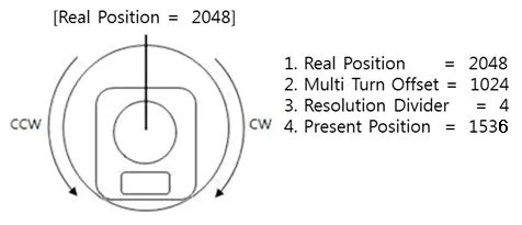
Multi Turn Offset (20)
Adjusts offset position. This offset value is added to the Present Position(36). Initial value is 0 and the range is from -24,576 to 24,576. DYNAMIXEL with a Present position of 2,048 with an offset of 1,024 will return an adjusted Present position of 3,072.

NOTE : The Multiturn Offset(20) and Resolution Divider(22) can be applied in Munti-turn Mode only (The condition that both CW and CCW are 0, see CW/CCW Angle Limit(6, 8) for more operation types.), otherwise, the set value in Multiturn Offset(20) and Resolution Divider(22) is ignored in different operation types.
Resolution Divider (22)
It allows the user to change DYNAMIXEL's resolution. The default Resolution Divider Value is set as 1. (1 ~ 4 available) When resolution is lowered, revolutions (in both directions) can be increased (up to 28 turns in each direction).
Present Position = Real Position / Resolution Divider
For example, a Real Position of 2048 with a Resolution Divider set as 2 will yield a Present Position value of 1024 (2048/2 = 1024). A DYNAMIXEL with Resolution Divider set as 2 will have a resolution 2048 for a single revolution. The Present Position can be obtained while Multi-turn Offset and Resolution Divider are taken into account.
Present position = (Real Position / Resolution Divider) + Multi-turn Offset
For example, a DYNAMIXEL with a Real Position of 2048 with a Resolution Divider set as 4 and Multi-turn Offset as 1024 will yield a Present Position of 1535 ((2048/4) + 1024 = 1535).
NOTE : The Multiturn Offset(20) and Resolution Divider(22) can be applied in Munti-turn Mode only (The condition that both CW and CCW are 0, see CW/CCW Angle Limit(6, 8) for more operation types.), otherwise, the set value in Multiturn Offset(20) and Resolution Divider(22) is ignored in different operation types.
Torque Enable (24)
| Value | Description |
|---|---|
| 0(Default) | Torque Off |
| 1 | Torque On |
LED (25)
The LED(65) determines LED On or Off.
| Bit | Description |
|---|---|
| 0(Default) | Turn OFF the LED |
| 1 | Turn ON the LED |
The LED is also used to indicate various statuses of the DYNAMIXEL actuator, refer to the following chart for more information.
| Status | LED Representation |
|---|---|
| Booting | LED blinks once |
| Factory Reset | LED blinks quickly 4 times |
| Shutdown Error | LED blinks continuously |
| Bootloader Mode | LED on continuously |
PID Gains (26, 27, 28)
The following is the block-diagram for the PID controller.
P gain: value of proportional band.I gain: value of integral action.D Gain: value of derivative action.
Gains values are in between 0 ~ 254.

- Kp : P Gain / 8
- Ki : I Gain * 1,000 / 2,048
- Kd : D Gain * 4 / 1,000
The relationship between Compliance Slop and PID
| Slope | P Gain |
|---|---|
| 8 | 128 |
| 16 | 64 |
| 32 | 32 |
| 64 | 16 |
| 128 | 8 |
The less the P gain, The larger the back lash, and the weaker the amount of output near goal position. At some extent, it is like a combined concept of margine and slope. It does not exactly match the previous concept of compliance. So it is obvious if you see the difference in terms of motion.
NOTE: PID control theory is not only limited to the control of motor(actuator) but is a generic theory that can be applied to all kinds of control. For more details about the PID controller, see PID Controller.
Goal Position (30)
Set the DYNAMIXEL's goal position through the Goal Position(30). 0 to 4,095 (0xFFF) is available. The unit is 0.088 [°]. If the Goal Position(30) is set over the CW/CCW Angle Limit(6, 8), the Status Packet transmits Angle Limit Error Bit (0x01) via its ERROR field. In the case, providing that Angle Limit Error Bit(0x01) in Alarm LED/Shutdown is set, the Alarm LED will start blinking and the motor's output will be 0 [%].

The picture above is the front view of DYNAMIXEL.
In multi-turn mode DYNAMIXEL has a range from -28,672 to 28,672 (can turn up to 7 revolutions in either CW or CCW direction). When resolution divider is set to a different value revolutions can increase.
NOTE : If it is set to Wheel Mode, Goal Position value is not used.
Moving Speed (32)
-
Join Mode, Multi-Turn mode
It is a moving speed to Goal Position. 0~1023 (0X3FF) can be used, and the unit is about 0.916rpm. If it is set to 0, it means the maximum rpm of the motor is used without controlling the speed. If it is 1023, it is about 937.1rpm. For example, if it is set to 300, it is about 274.8 rpm. However, the rpm will not exceed the No Load Speed.
-
Wheel Mode
It is a moving speed to Goal direction. 0
2047 (0X7FF) can be used, and the unit is about 0.916rpm. If a value in the range of 01023 is used, it is stopped by setting to 0 while rotating to CCW direction. If a value in the range of 1024~2047 is used, it is stopped by setting to 1024 while rotating to CW direction. That is, the 10th bit becomes the direction bit to control the direction.noteNOTE : Wheel mode allows to check max rpm. Any values higher than max rpm will not take effect.
Torque Limit (34)
It is the value of the maximum torque limit. 0 ~ 1,023(0x3FF) is available, and the unit is about 0.1%. For example, if the value is 512, it is about 50%; that means only 50% of the maximum torque will be used. When the power is turned on, Torque Limit(34) is reset to the value of Max Torque(14).
If the function of Alarm LED(17)/Shutdown(18) is triggered, the motor loses its torque because Torque Limit(34) becomes 0. Once error conditions are resolved and Torque Limit(34) is changed to the value other than 0, the motor can be operated again.
Present Position (36)
It is the present position value of DYNAMIXEL. The range of the value is 0~4095 (0xFFF), and the unit is 0.088 [°].
- The picture above is the front view of DYNAMIXEL.
In multi-turn mode, the range is from -28,672 to 28,672 with unit values dependent on Resolution Divider (0.088 * Resolution Divider)
NOTE : In multi-turn mode, Present position depends on resolution divider and multi-turn offset For more information turn to the section on Multi Turn offset and Resolution Divider.
NOTE : In multi-turn mode, Two's complement is applied for the negative value. For more information, please refer to Two's complement from Wikipedia.
Present Speed (38)
Is the current moving speed.
02047 (0x000 ~ 0x7FF) can be used.
If a value is in the rage of 01023 then the motor rotates to the CCW direction.
If a value is in the rage of 1024~2047 then the motor rotates to the CW direction.
The 10th bit becomes the direction bit to control the direction; 0 and 1024 are equal.
The value unit is about 0.916rpm.
For example, if it is set to 300 then the motor is moving to the CCW direction at a rate of about 274.8rpm.
Present Load (40)
It means currently applied load.
The range of the value is 02047, and the unit is about 0.1%.
If the value is 01,023, it means the load works to the CCW direction.
If the value is 1,024~2,047, it means the load works to the CW direction.
That is, the 10th bit becomes the direction bit to control the direction, and 1,024 is equal to 0.
For example, the value is 512, it means the load is detected in the direction of CCW about 50% of the maximum torque.
| Bit | 15 ~ 11 | 10 | 9 ~ 0 |
|---|---|---|---|
| Value | 0 | Load Direction | Data (Load Ratio) |
CCW Load : Load Direction = 0, CW Load : Load Direction = 1
Present load is an inferred value based on the internal output value; not a measured value using torque sensor, etc. Therefore, it may be inaccurate for measuring weight or torque. It is recommended to use it for predicting the direction and size of the force being applied to the joint.
Present Voltage (42)
It is the size of the present voltage supplied. This value is 10 times larger than the actual voltage. For example, when 10V is supplied, the data value is 100 (0x64)
For more details, see Min/Max Voltage Limit (12, 13).
Present Temperature (43)
It is the internal temperature of DYNAMIXEL in Celsius. Data value is identical to the actual temperature in Celsius. For example, if the data value is 85 (0x55), the current internal temperature is 85°C.
For more details, see Temperature Limit (11).
Registered Instruction (44)
Indicates whether the Write Instruction is registered by Reg Write Instruction
| Value | Description |
|---|---|
| 0 | No instruction registered by REG_WRITE. |
| 1 | Instruction registered by REG_WRITE exists. |
If ACTION instruction is executed, the Registered Instruction (44) will be changed to 0.
Moving (46)
| Value | Description |
|---|---|
| 0 | Goal position command execution is completed |
| 1 | Goal position command execution is in progress |
Lock (47)
| Value | Description |
|---|---|
| 0 | EEPROM area can be modified |
| 1 | EEPROM area cannot be modified |
CAUTION : If Lock is set to 1, the power must be turned off and then turned on again to change into 0.
Punch (48)
Minimum current to drive motor. This value ranges from 0x20 to 0x3FF.
Realtime-Tick (50)
The Realtime Tick(120) indicates DYNAMIXEL's time.
| Unit | Value Range | Description |
|---|---|---|
| 1 ms | 0 ~ 32,767 | The value resets to '0' when it exceeds 32,767 |
NOTE : This feature is available from Firmware v41.
Goal Acceleration (73)
This is Goal Acceleration value. It can be used from 0~254(0xFE) and the unit is approximately 8.583 [° / sec2]. When it is set to 0, there is no control over acceleration and moves with the maximum acceleration of the motor. When it is set to 254, it becomes 2,180 [° / sec2]. For example, the present speed of DYNAMIXEL is 0, and Goal Acceleration is 10. The speed of DYNAMIXEL after 1 second will be 14.3 [RPM].
Maintenance
Horn and Bearing Replacement
The horn is installed on the front wheel gear serration of the DYNAMIXEL whereas the bearing set is installed on the back.

Installing the Horn
Place the thrust horn washer into the actuator before inserting the horn. You must carefully align the horn to the wheel gear serration by aligning dots.

Once alignment is properly done, gently push the center of the horn toward the actuator. Make sure that the horn washer is in place as you tighten the bolt.
Installing the Bearing Set
You may need to remove the bearing set from the previous actuator and reinstall it into the new actuator. The bearing set can also be purchased separately. As bearing set is rotating freely, therefore alignment is not required when assembling to DYNAMIXEL.

Reference
NOTE Compatibility Guide Harness Compatibility
Videos
Connector Information
| Item | TTL |
|---|---|
| Pinout | 1 GND2 VDD3 DATA |
| Diagram | |
| Housing |  MOLEX 50-37-5033 |
| PCB Header |  MOLEX 22-03-5035 |
| Crimp Terminal | MOLEX 08-70-1039 |
| Wire Gauge for DYNAMIXEL | 21 AWG |
WARNING: To enhance user safety and to prevent proprietary risk or damage, be sure to check the pinout installed on DYNAMIXEL and the board. The Pinout of DYNAMIXEL may differ depending on a manufacturer of connector.
Communication Circuit
To control the DYNAMIXEL actuators, the main controller needs to convert its UART signals to the half duplex type. The recommended circuit diagram for this is shown below.
TTL Communication
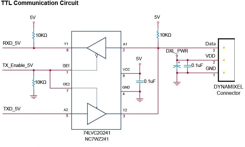
NOTE: Above circuit is designed for 5V or 5V tolerant MCU. Otherwise, use a Level Shifter to match the voltage of MCU.
The power of DYNAMIXEL is supplied via Pin1(-), Pin2(+). (The above circuit is built into DYNAMIXEL's controller only)
Drawings
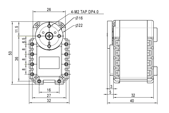
Please also checkout ROBOTIS Download Center for software applications, 3D/2D CAD, and other useful resources!